
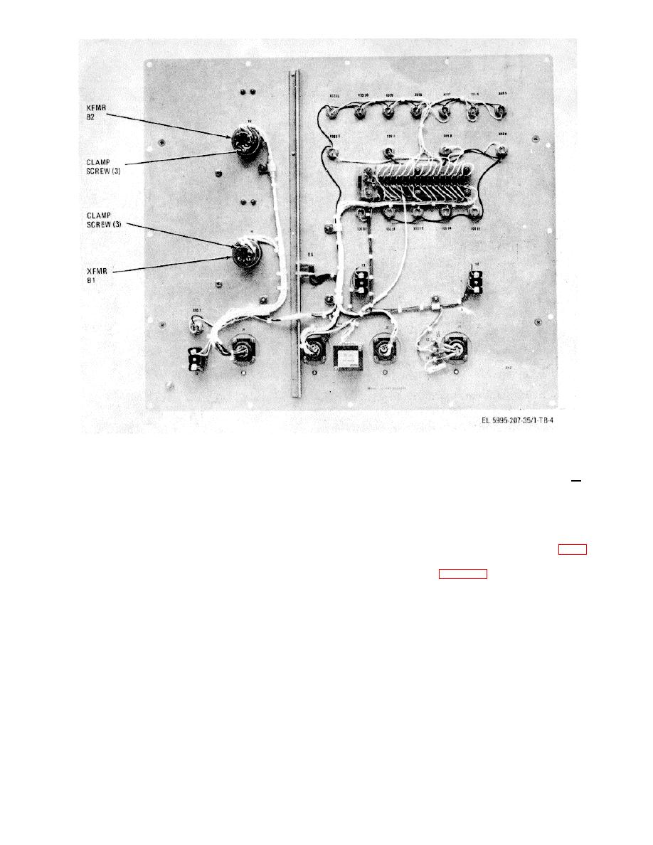
Figure 4. Locations Transformers B I and B2
(7) Check NAVIGATION GROUND SPEED
9. Navigation Ground Speed Transformer BI Fine
dial indication. The dial should indicate 225 -412 dial
Position. a. Performance Check.
division.
(1)
Deenergize 115 vac, 400 Hz primary power
b. Adjustments.
circuit.
(1) Set NAVIGATION GROUND SPEED dial at
(2) Disconnect electronic voltmeter from barrier
225 and lock dial at this setting with dial lock (fig. 1).
strip and disconnect and remove all barrier strip jumper
wires.
(2) Refer to figure 4. Loosen the three clamp
screws that secure case of transformer B1.
(3) Install jumper wires between terminals B and
J, A and C, and A and II of barrier strip.
(3) Observe electronic voltmeter and slowly turn
transformer case to minimize indication on electronic
(4) Connect electronic voltmeter to terminals E
and F of barrier strip with test leads.
(4) Tighten the three clamp screws that secure
(5) Unlock NAVIGATION GROUND SPEED dial
case of transformer B1.
lock. Then energize 115 vac, 400 Hz primary power
circuit.
10.
Navigation Drift Transformer
B2
Coarse
Position. a. Performance Check.
(6)
Observe electronic voltmeter and carefully turn
NAVIGATION GROUND SPEED dial to minimize
indication
on
electronic
6
