
TB 9-4920-460-24
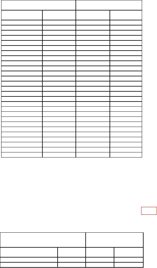
Table 6. TxRamp COMM DAC Table Adjustment Continued.
Measuring receiver indications
Test instrument
(dBm)
Frequency settings
Power output
Min
Max
(MHz)
(dBm)
108
0
-2.5
+2.5
115
0
-2.5
+2.5
125
0
-2.5
+2.5
135
0
-2.5
+2.5
145
0
-2.5
+2.5
155
0
-2.5
+2.5
165
0
-2.5
+2.5
174
0
-2.5
+2.5
225
0
-2
+2
235
0
-2
+2
245
0
-2
+2
255
0
-2
+2
265
0
-2
+2
275
0
-2
+2
285
0
-2
+2
295
0
-2
+2
300
0
-2
+2
310
0
-2
+2
320
0
-2
+2
330
0
-2
+2
340
0
-2
+2
350
0
-2
+2
360
0
-2
+2
370
0
-2
+2
380
0
-2
+2
390
0
-2
+2
400
0
-2
+2
(13) Use the up or down arrow keys on the keypad, until MB is displayed.
NOTE
The up / down arrow keys will advance to VOR, LOC, GS, and
ILS modes. The left / right keys will change frequencies within
selected mode.
(14) If measuring receiver does not indicate within limits specified in table 7 for each
mode selected, use the TI RF OUTPUT toggle switch to adjust TI to as close as possible to
nominal.
Table 7. TxRamp MB DAC Table Adjustment.
Measuring receiver
Test instrument
indications
(dBm)
Power out
Mode
Min
Max
(dBm)
MB 75 MHz
13
+11
+15
L/V 108.05 MHz
6
+3.5
+8.5
15