TB 9-4920-460-24
(2) Set TI FUNCTION switch to VOR.
(3) Connect TI RT connector directly to measuring receiver (no sensor).
(4) Toggle TI AC power switch then toggle TI DC switch to turn TI on.
(5) Configure AMR software for Input to RF, Meas to VOR, DUT Power to -25 dBm,
Ext. Loss to 1.00, RF Tuning to 108.000, PSA to Connect, Control to Continuous then Start.
(6) If AMR Freq 30 Hz boxes do not indicate 30 Hz 0.3 Hz and 30% 2%, perform b
(1) below.
(7) If AMR Freq 9960 Hz boxes do not indicate 9960 Hz 99 Hz and 30% 2%,
perform b (2) below.
(8) If AMR Freq 30+9960 box does not indicate 60% 3%, perform b (1) and (2)
below.
(9) Toggle and hold TI MB NAV ID switch to down position. Add Freq 1000 Hz
Modulation box and 30+9960 box indication values. If calculated value is not 70% 3%,
perform b (1) and (2) below.
(10) Release TI MB NAV ID switch to center position.
b. Adjustments
(1) Adjust R48 (fig. 3) for an AMR modulation box indication of 30%.
(2) Adjust R16 (fig. 3) for an AMR modulation box indication of 30%.
10. VOR Angle
a. Performance Check
(1) Set TI ILS/VOR switch to OC/0 position.
(2) Connect TI RT connector directly to measuring receiver (no sensor).
(3) Configure AMR software for Input to RF, Meas to VOR, DUT Power to -25 dBm,
Ext. Loss to 1.00, RF Tuning to 108.000, Avg ON (Norm) set to 5, PSA to Connect, Control
to Continuous then Start.
(4) If AMR VOR Bearing box indication is not between 179 and 181 degrees,
perform b below.
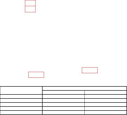
(5) Check TI ILS/VOR switch settings listed in table 10. If AMR indications are not
within limits specified in table 10, perform b below.
Table 10. VOR Angle Accuracy.
AMR indications (degrees)
TI ILS/VOR switch
settings
Min
Max
U1/R1/45
224
226
FS/135
314
316
OC/180
359
1
FS/225
44
46
D1/L1/315
134
136
b. Adjustments

