TB 9-4920-460-24
(1) Ensure TI ILS/VOR switch is at the 180 position.
(2) Table 11 shows the degree offset of each switch section of A7S1.
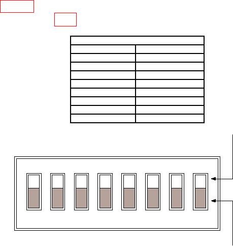
(3) Adjust A7S1 (fig. 4) until TI indicator is within tolerance.
Table 11. A7S1.
A7S1 Sections
Section
Degree offset
1
0.18
2
0.35
3
0.70
4
1.41
5
2.81
6
5.62
7
11.25
8
22.50
ON Position
1
OFF Position
Figure 4. A7S1 Adjustment.
11. LOC Modulation
a. Performance Check
(1) Set TI FUNCTION switch to LOC and ILS/VOR switch to OC/0 position.
(2) Connect TI RT connector directly to measuring receiver (no sensor).
(3) Configure AMR software for Input to RF, Meas to ILS Localizer, DUT Power to
-25 dBm, Ext. Loss to 1.00, RF Tuning to 108.100, PSA to Connect, Control to Continuous
then Start.
(4) If AMR Freq 90 Hz boxes do not indicate 90 Hz 0.9 Hz and 20% 2%, perform b
below.
(5) If AMR Freq 150 Hz boxes do not indicate 150 Hz 1.5 Hz and 20% 2%, perform
b below.
(6) If AMR SMD box does not indicate 40% 2%, perform b below.

