
TB 9-4931-287-40
NOTE
Repeat (2) above as necessary during remainder of this
procedure to assure stability of TI. Instability is often caused
by internal batteries and should be corrected before proceeding
with the calibration.
(3) Connect equipment as shown in figure 1, connection A.
(4) Set FUNCTION switch to OUTPUT X1. Null detector will indicate between
0 and 20 V.
(5) Connect equipment as shown in figure 1, connection B.
(6) Set dc voltage divider controls to .1000000.
(7) Adjust output of calibrator to 0.10000 V and set MILLIVOLT switch to 10.
(8) Readjust calibrator to obtain best null on null detector.
Calibrator will
indicate between 0.09975 and 0.10025 V.
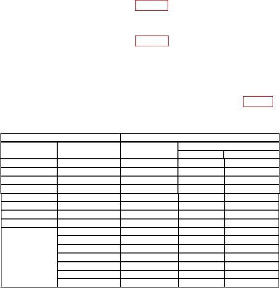
(9) Repeat technique of (7) and (8) above, using values listed in table 5. Calibrator
will indicate within limits specified.
Table 5. Output Accuracy
Test instrument
Calibrator
MILLIVOLT
MILLIVOLT
Final setting (V)
Initial setting
switch setting
control setting
(V)
Min
Max
20
0
0.2
0.19970
0.20030
30
0
0.3
0.29965
0.30035
40
0
0.4
0.39960
0.40040
50
0
0.5
0.49955
0.50045
60
0
0.6
0.59950
0.60050
70
0
0.7
0.69945
0.70055
80
0
0.8
0.79940
0.80060
90
0
0.9
0.89935
0.90065
1
100
0
1.0
0.99930
1.00070
2
1.02
1.01929
1.02071
4
1.04
1.03928
1.04072
6
1.06
1.05927
1.06073
8
1.08
1.07926
1.08074
10
1.10
1.09925
1.10075
11
1.11
1.10924
1.11076
1Do
not change MILLIVOLT switch setting.
(10) Adjust output of calibrator to 0.111 V and set FUNCTION switch to OUTPUT X.1.
(11) Readjust calibrator to obtain best null on null detector. Calibrator output will
be between 0.11089 and 0.11111 V.
b. Adjustments. No adjustments can be made.
9