
TB 9-4931-287-40
Table 6. Milliamperes
Test instrument
Multimeter indications (mV)
MILLIVOLT
MILLIVOLT
Min
Max
switch
control
30
0
29.95
30.05
40
0
39.94
40.06
50
0
49.93
50.07
60
0
59.92
60.08
70
0
69.91
70.09
80
0
79.90
80.10
90
0
89.89
90.11
1
100
0
99.88
100.12
1
100.87
101.121
3
102.87
103.123
5
104.87
105.125
7
106.87
107.127
9
108.87
109.129
11
110.86
111.131
1Do
not change MILLIVOLT switch setting.
b. Adjustments
(1) Position controls as listed in (a) through (c) below:
(a) MILLIVOLT switch to 100.
(b) MILLIVOLT control to 0.
(c) FUNCTION switch to MEASURE X1 mA.
(2) Position plugs in dc current shunt for 100 mA.
(3) Adjust output of dc power supply to obtain multimeter indication of 100.00 mV.
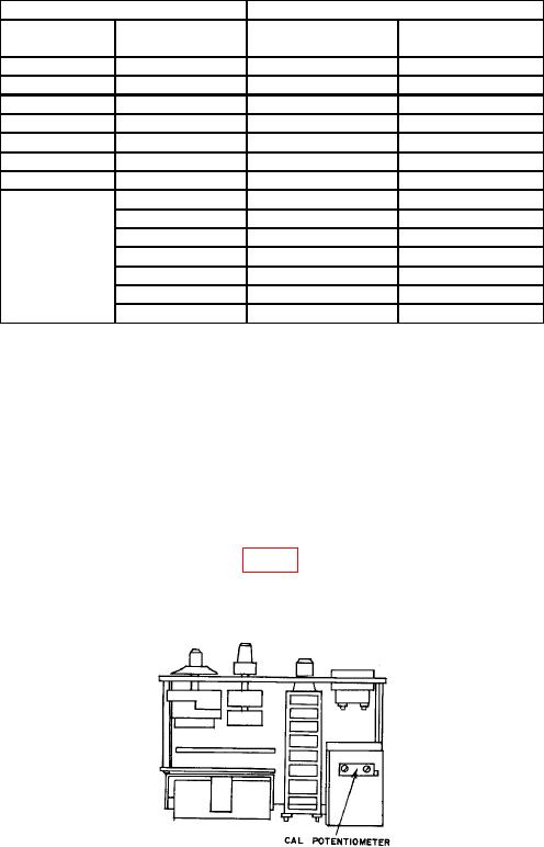
(4) Adjust CAL potentiometer (fig. 3) while pressing DET switch until TI meter
indicates a null (R).
Figure 3. Model 72-311 - top chassis review.
18. Final Procedure
a. Deenergize and disconnect all equipment and reinstall TI protective cover.
b. Annotate and affix DA label/form in accordance with TB 750-25.
11(12 Blank)