
TB 9-4931-495-24
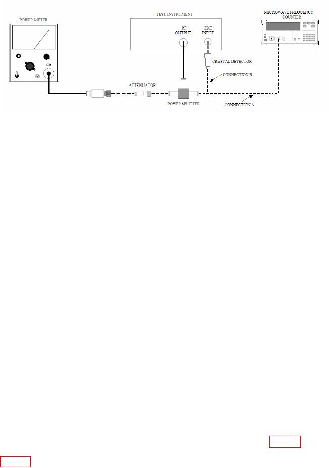
Figure 6. Frequency and power output - equipment setup.
(2) Position controls as listed in (a) through (m) below:
(a) BAND selector to the frequency of the plug-in installed.
(b) START MARKER pointer to low end of frequency range.
(c) CW MARKER pointer to midrange.
(d) STOP MARKER pointer to high end of frequency range.
(e) MODE switch to MANUAL.
(f) TRIGGER switch to INT.
(g) TIME-SECONDS switch to 0.1-0.01.
(h) 1 kHz SQ WV/OFF (rear panel) to OFF.
(i) RF BLANKING switch (rear panel) to OFF.
(j) ALC switch to INT (or EXT if INT leveling option not applicable).
(k) RF switch to ON (not applicable to some models).
(l) TIME-SECONDS vernier control fully cw.
(m) FM-NORM-PL switch (rear panel) to NORM (not applicable to
some models).
(3) Press CW pushbutton and turn POWER LEVEL control cw for maximum
leveled power out.
NOTE
Adjust CW MARKER pointer from low to high end of
frequency dial several times and approach the setting from the
low frequency end.
(4) Set CW MARKER pointer to frequency settings listed in table 8. if microwave
frequency counter does not indicate within limits specified, perform adjustments shown in
22