
TB 9-4931-537-24
(2) Set multimeter for 4 wire resistance measurements by pressing:
FUNCTION/RANGE blue colored pushbutton then the OHM/OHMF pushbutton. Set O
Comp to ON by pressing MENU Offset Comp Ω pushbutton, followed by
NUMERIC/USER 1 and Enter pushbuttons.
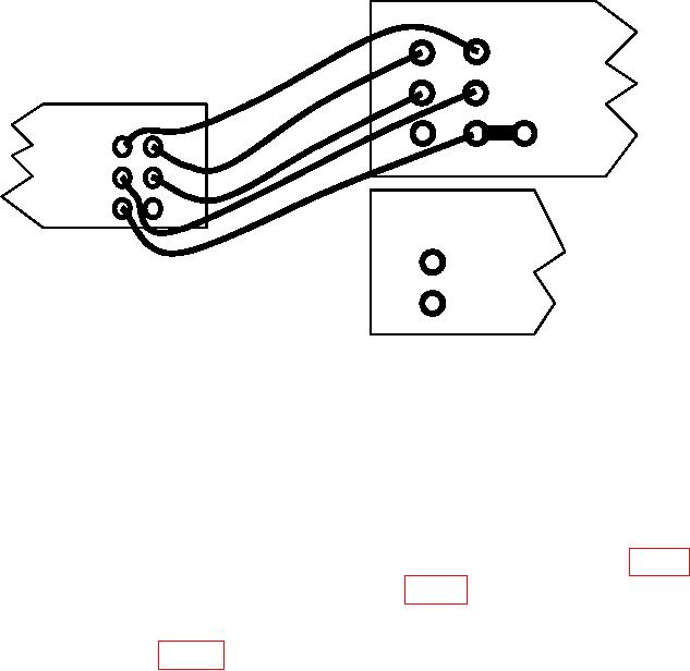
CALIBRATOR
OUTPUT SENSE
HI
HI
MULTIMETER
LO
LO
SENSE INPUT
HI
HI
GUARD GROUND
LO
LO
CURRENT
GUARD
I
OUTPUT
HI
LO
AMPLIFIER
Figure 3. Resistance.
(3) Set calibrator for a 0 Ω output. Set calibrator's EX SNS to on (illuminated). Set
2 wire Comp soft-key to OFF.
(4) Multimeter indication will be 00.00000 (8 digits). Record indication in table 1.
(5) Set calibrator to (k, M) Ω outputs listed in table 1. At each resistance output,
adjust the calibrator output adjustment control knob for a calibrator control display reading
equal to multimeter indication. The calibrator control ERROR display indication will be
within specified limits of table 1. Record calibrator ERROR display indication in space
provided.
(6) Set calibrator to STANDBY, then press RESET pushbutton.
i. Wideband. Calibrator, Fluke, Model 5720A/( ), and Agilent, Model 3458A.
(1) Connect Calibrator Wideband output to Multimeter Input Hi and Lo terminals
through cable and 50 ohm termination supplied with Calibrator.
(2) Press multimeter FUNCTION/RANGE ACV pushbutton.
8