
TB 9-4931-538-40
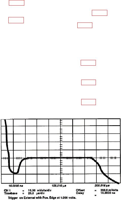
e. Adjust RC1 (fig. 12) on the vertical assembly A2 until the positive and negative
pulse peaks are equidistant from the flat portion of the pulse, VP = VN. The Delta V
Markers can help determine when the pulses are equidistant (fig. 23).
f. Adjust CC1 (fig. 12) on vertical assembly A2 until the positive and negative plus
peaks are lowest in amplitude. Readjust RC1 and CC1 (fig. 12) until the pulse top is as flat
as possible.
g. Press Channels key and set Channel 1 VOLTS/DIV to Sensitivity = 1 mV and
OFFSET to Offset = 300.0 mV.
h. Do not turn Channel 1 display Off. Set Channel 2 display On and move semi-
rigid cables from Channel 1 to Channel 2.
i. Repeat e and f above except adjust RC2 and CC2 (fig. 12).
j. Set Channel 2 display Off and Channel 3 display On. Move semi-rigid cables
from Channel 2 to Channel 3.
k. Repeat e and f above except adjust RC3 and CC3 (fig. 12).
l. Set Channel 3 display Off and Channel 4 display On. Move semi-rigid cables
from Channel 3 to Channel 4.
m. Repeat e and f above except adjust RC4 and CC4 (fig. 12).
n. Remove semi-rigid cables from TI.
Figure 22. Feedthrough not compensated.
43