
TB 9-4931-538-40
Figure 23. Adjusting RC1 for equidistant pulse peaks.
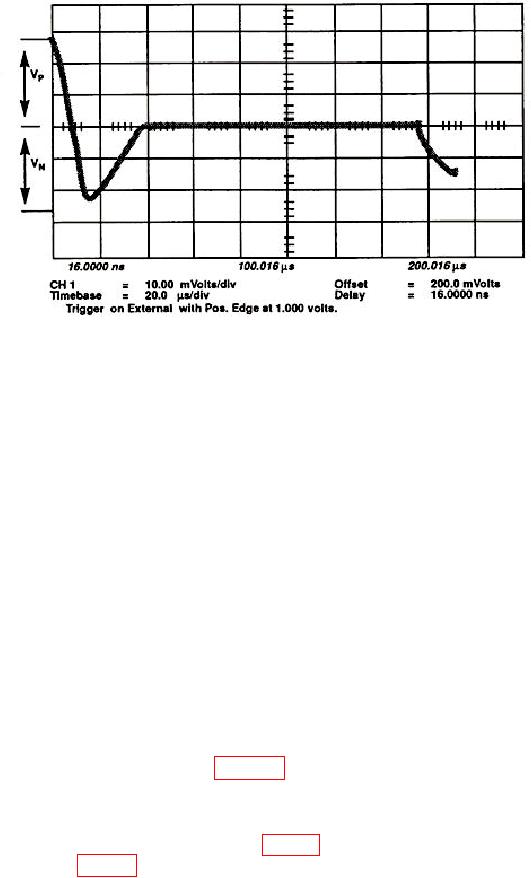
26. Trigger Adjustment
a. Set the display menu and mainframe settings to meet the following conditions:
(1) Press Display key. Display Mode to Average is highlighted. NUMBER OF
AVERAGES to # Averages = 4. Screen to Single is highlighted. Graticule to Grid is
highlighted. Bandwidth to 12.4 GHz is highlighted.
(2) Press Channels key. Channel 1 display On is highlighted. Channel 2
through 4 display Off is highlighted. VOLTS/DIV to Sensitivity = 10.00 mV/div.
OFFSET to Offset = 0.000 V. PROBE ATTEN to Chl Atten Factor = 1.000.
(3) Press Timebase key. TIME/DIV to Sweep Speed 1.00 ms/div. DELAY to
Delay = 16.000 ns. Delay Ref at Left is highlighted. Freerun/ Trg'd Sweep to Trg'd is
highlighted.
(4) Press Trigger key. TRIGGER LEVEL to Trigger Level = 0.000 V. HF Sens
to Off is highlighted. HF Reject to Off is highlighted. Attenuation to 1.
(5) Press Network key. Reflect/Trans/Cal to Reflect is highlighted. Step &
Chan 1 to Off is highlighted.
b. Connect equipment as shown in figure 7, CONNECTION A.
d. One period of the 100 kHz sine wave with an amplitude of approximately 50 mV p-p
will be on the display. If not, adjust HYST (fig. 11) horizontal assembly A1 fully ccw and
adjust the OFFSET (fig. 11) to center the starting point on the left side of the display.