
TB 9-4931-538-40
c. Press Timebase and DELAY keys. Set to Delay = 18 ns and press Freerun/Trg'd
Sweep key until Trg'd is highlighted.
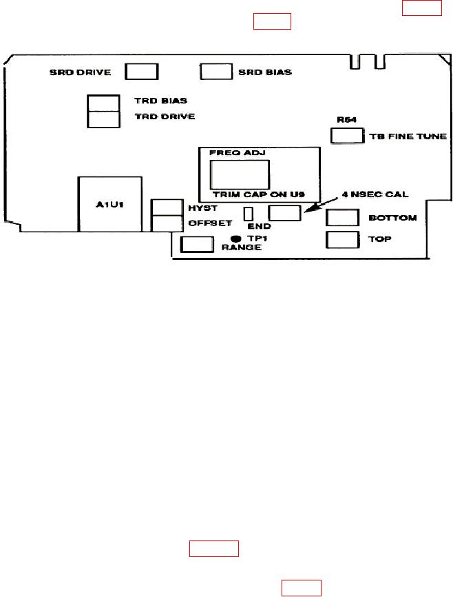
d. Connect the positive lead of multimeter to horizontal assembly A1TP1 (fig. 11) and
negative to chassis ground and adjust the RANGE (fig. 11) for 5 V (R).
Figure 11. Horizontal assembly A1 adjustments.
19. Step Recovery Diode Adjustment
a. Set the display menu and mainframe settings to meet the following conditions:
(1) Press Display key. Display Mode to Average is highlighted. NUMBER OF
AVERAGES to # Averages = 4. Screen to Single is highlighted. Graticule to Grid is
highlighted. Bandwidth to 12A GHz is highlighted.
(2) Press Channels key. Channel 1 to display On is highlighted. Channel 2
through 4 display Off is highlighted. VOLTS/DIV to Sensitivity = 20.00 mV/div for
Channel 1 through 4. OFFSET to Offset = 0.000V. PROBE ATTEN to Chl Atten
Factor = 1.000.
(3) Press Timebase key. TIME/DIV to Sweep Speed = 500 ps/div. DELAY to
Delay = 16.0000 ns. Delay Ref at Left is highlighted. Freerun/Trg'd Sweep to Trg'd
is highlighted.
(4) Press Trigger key. TRIGGER LEVEL to Trigger Level = 0.000 V. Slope
Pos to Pos is highlighted. PROBE ATTEN to Ext Atten Factor = 1.000. HF Sens to
Off is highlighted. HF Reject to Off is highlighted.
b. Connect equipment as shown in figure 5.
d. Preset LB1 and OG1 on the vertical assembly A2 (fig. 12) to mechanical center.