
TB 9-4931-540-24
Table 9. Noise
RBW-VBW-ST
SWEEP ENTRY
Average marker
ENTRY RES BW
MANUAL
amplitude
settings
settings
indications
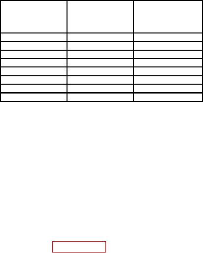
(kHz)
(dBm)
10
kHz
100
<-104
3
kHz
30
<-108
1
kHz
10
<-111
300
Hz
10
<-115
100
Hz
10
<-122
30
Hz
10
<-127
10
Hz
10
<-132
3
Hz
10
<-137
(13) Press keys and enter values using ENTRY keys as listed in (a) through (e) below:
ENTRY blue shift and then ENTRY CAL OFF.
(a)
SWEEP ENTRY MANUAL to 40 Hz.
(b)
RBW-VBW-ST ENTRY RES BW to 3 Hz.
(c)
ENTRY blue shift and then ENTRY CAL ON.
(d)
MARKER/CONTINUOUS ENTRY NOISE LVL to on.
(e)
NOTE
Wait until (1 Hz) is displayed behind TI marker amplitude
dBm indication before proceeding to (14) below.
(14) Average TI marker amplitude indication will be <-123 dBm.
b. Adjustments. Refer to paragraph 6 d.
15. Low Frequency Response
a. Performance Check
(1) Ensure TI front panel inputs are open.
NOTE
60 Hz represents power line frequency; if power line frequency
is different than 60 Hz, use current power line frequency in (2)
(g) and (h) below.
(2) Press keys and enter values using ENTRY keys as listed in (a) through (i) below:
ENTRY INSTR PRESET.
(a)
INPUT AUTORANGE to off.
(b)
INPUT ENTRY RANGE to -25 dBm using ENTRY STEP .
(c)
ENTRY REFERENCE LEVEL to -75 dBm.
(d)
RBW-VBW-ST ENTRY RES BW to 3 Hz.
(e)
RBW-VBW-ST ENTRY VIDEO BW to 1 Hz.
(f)