
TB 9-5120-212-35
(1) If TI indication error is the same in both cw and ccw directions, adjust pointer of
TI dial indicator.
(2) If TI indication error is not the same in both directions, perform (3) through (10)
below.
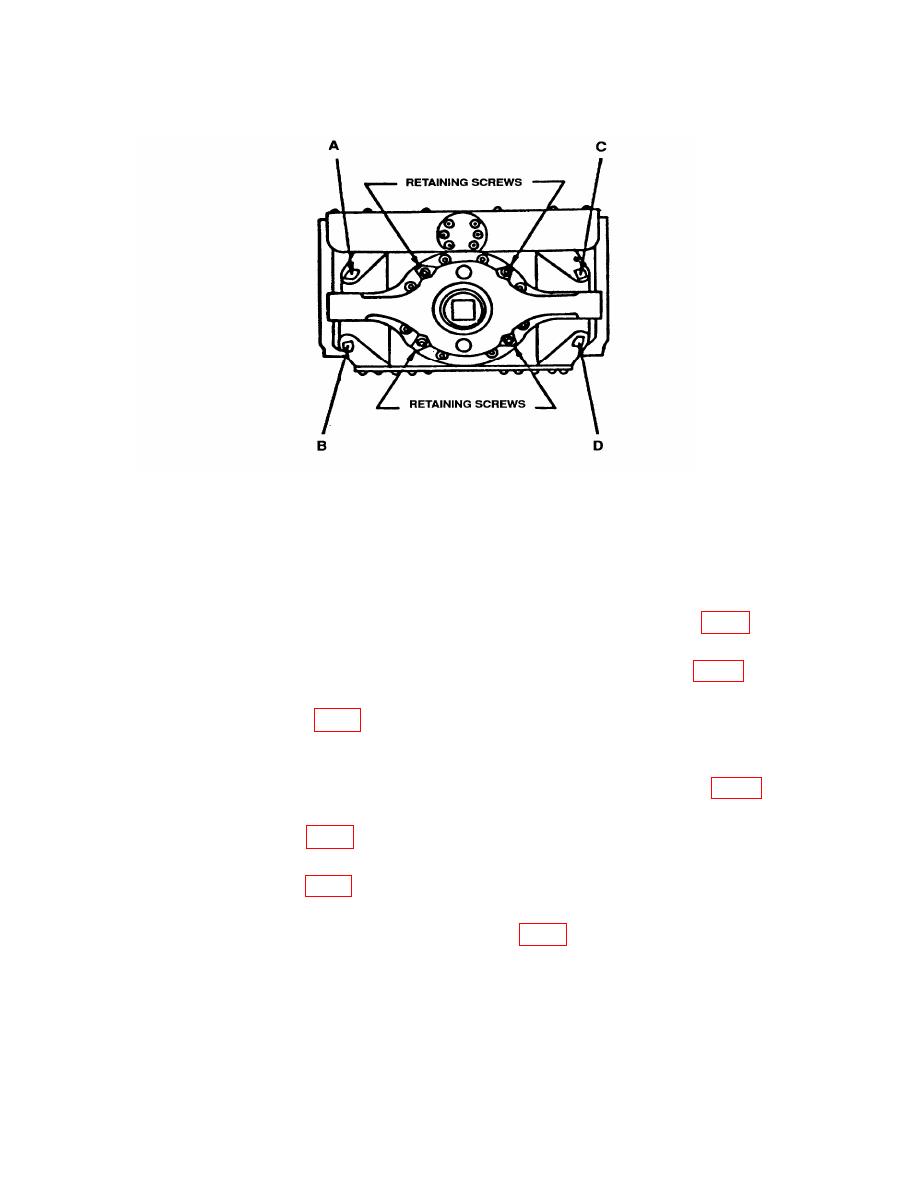
(3) Remove sealant from the four adjustment screws A, B, C, and D (fig. 1) on the
back of TI.
(4) Using appropriate size Allen wrench, back off screws A and B (fig. 1) at least
three turns.
(5) Adjust screw C (fig. 1) until a pressure reading is shown on indicator, then back
off screw until indication returns to 0.
(6) Check spacing between the reaction arm on sensing unit housing and reaction
ears. If reaction arm is not centered between ears, adjust screws C and D (fig. 1) until
sensor is centered.
(7) Turn screw A (fig. 1) inward until a pressure reading is shown on indicator and
then back off to 0 plus one-quarter additional turn.
(8) Turn screw B (fig. 1) inward until a pressure reading is shown on indicator and
back off to 0.
(9) Repeat a above and adjust screws B and C (fig. 1) slightly to bring TI indications
within tolerance (R).
7
