
TB 9-5120-212-35
(10) Reseal retaining screws with sealant. Repeat table 4.
(11) Operate crank cw to obtain an indication of 800 ft-lbs (1200 ft-lbs for models
DPT-2500 and DPT-2500R) on force/torque indicator.
for models DPT-2500 and DPT-2500R) on digital display (R).
NOTE
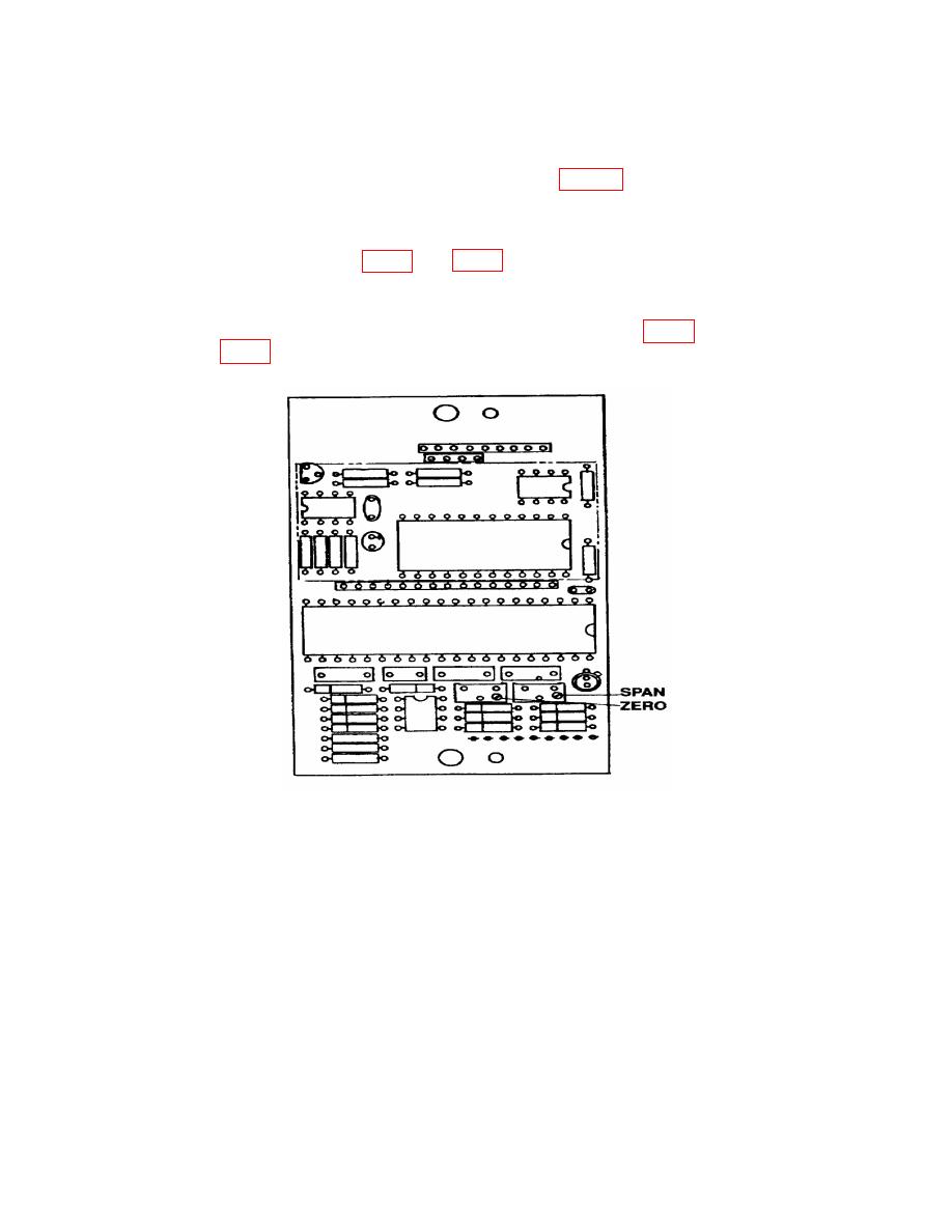
It should not be necessary to adjust internal ZERO (fig. 2 and
8
