
TB 9-5855-1891-40
(3) Turn SMALL CENTER MICROMETER VERTICAL AND HORIZONTAL
CONTROLS (fig. 3) to adjust horizontal and vertical reticles until centered on
STATIONARY RETICLE (fig. 3).
(4) Look through HORIZONTAL VIEWER (fig. 3), hold SMALL CENTER
MICROMETER HORIZONTAL CONTROL and turn OUTER MICROMETER
HORIZONTAL CONTROL until HORIZONTAL INDICATOR (fig. 3) indicates 0.
(5) Look through VERTICAL VIEWER (fig. 3), hold SMALL CENTER
MICROMETER VERTICAL CONTROL and turn OUTER MICROMETER VERTICAL
CONTROL until VERTICAL INDICATOR (fig. 3) indicates 0.
(6) Repeat (3), (4), and (5) above until horizontal and vertical alignment cannot
be improved.
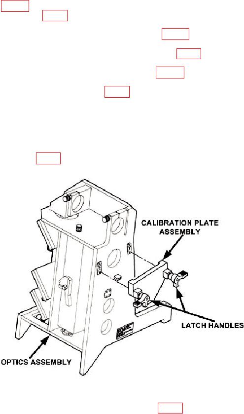
(7) Remove CALIBRATION PLATE ASSEMBLY from container case and install
CALIBRATION PLATE ASSEMBLY on OPTICS ASSEMBLY by pushing in and turning
two LATCH HANDLES (fig. 4).
Figure 4. Optics and calibration plate assemblies.
(8) Move UPPER MIRROR OPTICAL BAFFLE (fig. 5) to open and close all other
optical baffles (block light path).
7