
TB 9-5855-1891-40
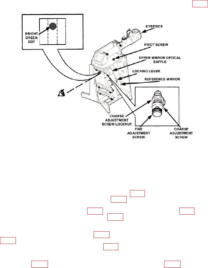
(9) Release LOCKING LEVER and tighten PIVOT SCREW (if necessary) so
REFERENCE MIRROR will stay in any position without use of LOCKING LEVER (fig. 5).
Figure 5. Optics assembly alignment.
NOTE
"Out" position means apertures are open for passage of light
from boresight collimator mounting position. "In" position
means apertures are not open for passage of light from
boresight collimator mounting position.
(10) Move REFERENCE MIRROR to out position (fig. 5). Do not use LOCKING
LEVER to lock REFERENCE MIRROR in place (fig. 5).
reflected image. If STATIONARY RETICLE (fig. 6) reflected image is not seen, perform
b (l) through (5) below.
(12) Look through EYEPIECE (fig. 5) and turn FINE ADJUSTMENT SCREWS
(fig. 5) to adjust elevation and azimuth of STATIONARY RETICLE REFLECTED IMAGE
until it is on top of STATIONARY RETICLE (fig. 6).
(13) Release LATCH HANDLES on calibration plate and remove from OPTICS
case cover.
8