
TB 9-5915-215-40
(4) Set TI AUTO/MANUAL/SELECT switch to the center position, MANUAL
(manual operation), and set the thumb wheels to select range 01.
Press the
AUTO/MANUAL/SELECT switch down momentarily to activate the TI range.
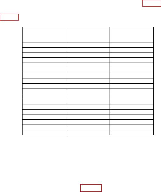
(5) Measuring receiver will indicate within the limits listed in table 3.
(6) Repeat technique of (2) through (5) above for remaining ranges and frequencies
listed in table 3.
Table 3. Insertion Loss
Signal generator
Measuring receiver
frequency
indication
Range
(Hz)
(dB)
2
01
135
k
2
02
300
k
2
03
600
k
2
04
1.0
M
2
05
2.0
M
2
06
3.2
M
2
07
5.0
M
2
08
6.3
M
2
09
10.0
M
2
10
16.0
M
2
11
25.0
M
2
12
40.0
M
2
13
70.0
M
2
14
100.0
M
2
15
150.0
M
2
16
270.0
M
2
17
600.0
M
2
18
1000
M
(7) Set signal generator RF OUTPUT to off and disconnect measuring receiver
from TI.
b. Adjustments. No adjustments can be made.
9. Harmonic Rejection
a. Performance Check
(1) Connect equipment as shown in figure 2.
(2) Set TI AUTO/MANUAL/SELECT switch to the center position, MANUAL
(manual operation), and set the thumb wheels to select range 01.
Press the
AUTO/MANUAL/SELECT switch down momentarily to activate the TI range.
(3) Set signal generator to produce a 135 kHz CW output at 0 dBm.
frequency and span to 250 kHz.