
TB 9-6625-011-24
(14) Repeat technique of (9) through (12) above for TI 0.3 VOLTS RANGE switch
formula. TI frequency response error will be within the limits specified; if not, perform b
15) through (17).
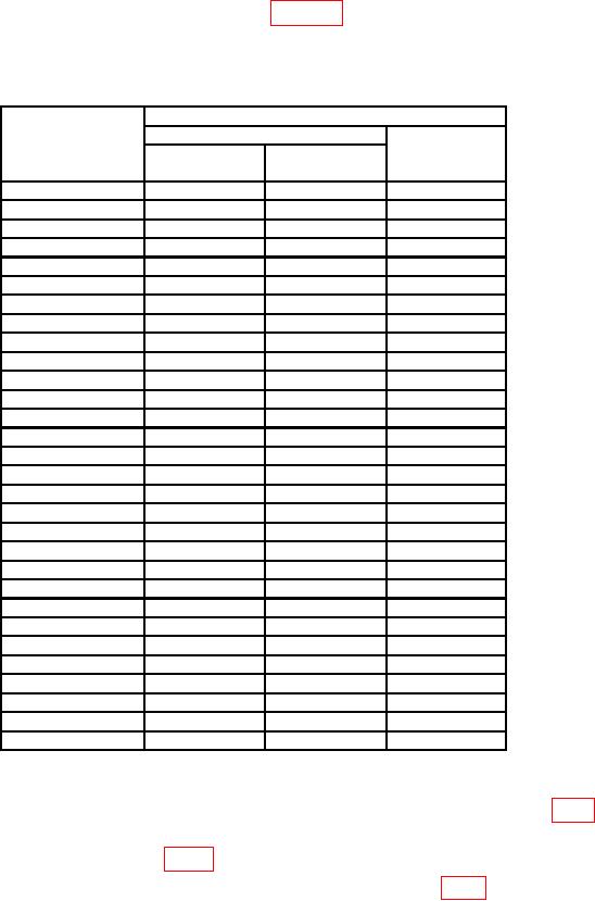
Table 4. Frequency Response
Calibrator
Test instrument
Output
RANGE
Limits
Initial setting
switch settings
(%)
(Volts)
.001
0.001
400
Hz
N/A
.001
0.001
20
Hz
5.0
.001
0.001
10
kHz
1.0
.001
0.001
50
kHz
1.0
.001
0.001
100
kHz
1.0
.001
0.001
500
kHz
1.0
.001
0.001
1.0 MHz
1.0
.001
0.001
2.0 MHz
2.0
.001
0.001
3.0 MHz
3.0
.001
0.001
10
MHz
5.0
1
1
400
Hz
N/A
1
1
20
Hz
5.0
1
1
10
kHz
1.0
1
1
50
kHz
1.0
1
1
100
kHz
1.0
1
1
500
kHz
1.0
1
1
1.0 MHz
1.0
1
1
2.0 MHz
2.0
1
1
3.0 MHz
3.0
1
1
10
MHz
5.0
.3
0.3
400
Hz
N/A
.3
0.3
20
Hz
5.0
.3
0.3
10
kHz
1.0
.3
0.3
50
kHz
1.0
.3
0.3
100
kHz
1.0
.3
0.3
500
kHz
1.0
.3
0.3
1.0 MHz
1.0
.3
0.3
2.0 MHz
2.0
.3
0.3
3.0 MHz
3.0
.3
0.3
10
MHz
5.0
b. Adjustments
(1) Adjust R4 (R627 for TIs with amplifier board A6, P/N 03400-66512) (fig.1) until
multimeter indicates -1.00 V.
(2) If necessary, adjust R6 (fig. 1) for full-scale indication on TI.
(3) Set calibrator for a 10 mV, 400 Hz output. Adjust R6 (fig.1) until TI indicates
full scale (R).
(4) Set RANGE switch to .1 VOLTS.