
TB 9-6625-1098-24
8. Voltmeter Accuracy
a. Performance Check
(1) Remove shorting bar connecting TI circuit ground to chassis ground.
(2) Set FUNCTION switch to VOLTMETER.
(3) Connect calibrator OUTPUT to ratio standard INPUT and connect ratio
transformer OUTPUT to TI INPUT.
(4) Set METER RANGE switch to .0003 VOLTS and adjust ratio transformer for a
0.01 ratio.
(5) Adjust calibrator frequency for 1 kHz and 0.0003 V indication on TI meter.
Calibrator will indicate between 29.4 and 30.6 mV.
(6) Set METER RANGE switch to .001 VOLTS.
(7) Adjust calibrator frequency for 400 Hz and 0.001 V indication on TI meter. If
calibrator does not indicate between 0.098 and 0.102 V, perform b below.
(8) Place calibrator in STBY and remove calibrator connection from ratio standard
and connect directly to TI INPUT.
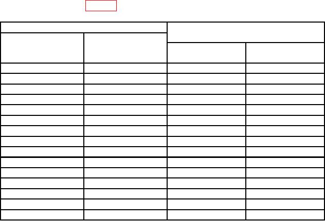
(9) Repeat technique of (6) and (7) above for METER RANGE switch settings and
meter indications listed in table 3 below. Calibrator will indicate within limits specified.
Table 3. Voltmeter Accuracy
Calibrator indications
Test instrument
(V)
METER RANGE
Meter
switch settings
indications
(VOLTS)
(V)
Min
Max
0.003
0.003
0.00294
0.00306
0.01
0.01
0.0098
0.0102
0.03
0.03
0.0294
0.0306
0.1
0.1
0.098
0.102
0.3
0.3
0.294
0.306
1
0.2
0.18
0.22
1
0.4
0.38
0.42
1
0.6
0.58
0.62
1
0.8
0.78
0.82
1
1
0.98
1.02
3
3
2.94
3.06
10
10
9.8
10.2
30
30
29.4
30.6
100
100
98.0
102.0
300
300
294.0
306.0
b. Adjustments
(1) Adjust calibrator for a 0.1 V, 400 Hz output.