
TB 9-6625-1098-24
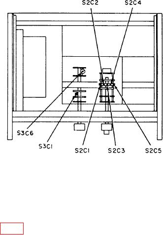
Figure 2. Distortion analyzer - bottom view.
(13) Adjust calibrator frequency to 1 kHz and amplitude control for a 3 V indication
on TI meter. Set the reference level on calibrator by pressing the NEW REF key.
(14) Adjust calibrator frequency to 200 kHz and output amplitude for 0.0% error
display reading.
(15) Adjust S3C1 (fig. 2) for a 3 V indication on TI meter (R).
10. High Pass Filter (Hewlett-Packard, Models 333A and 334A)
a. Performance Check
(1) Connect calibrator OUTPUT to TI INPUT.
(2) Position TI switches as listed in (a) through (c) below:
(a) METER RANGE to .3 VOLTS.
(b) FUNCTION to SET LEVEL.
(c) HIGH PASS FILTER to IN.
(3) Set calibrator to VOLT operation and adjust frequency to 5 kHz and amplitude
for a 0.3 V indication on TI meter.
(4) Adjust TI SENSITIVITY controls for meter indication of 0 dB.
(5) Adjust calibrator frequency to 1 kHz, and verify TI meter indicates within 0.5 dB
of 0 dB setting.
(6) Adjust calibrator frequency to 60 Hz, and verify TI meter indicates at least
40 dB below the 0 dB setting.
b. Adjustments. No adjustments can be made.