
TB 9-6625-111-24
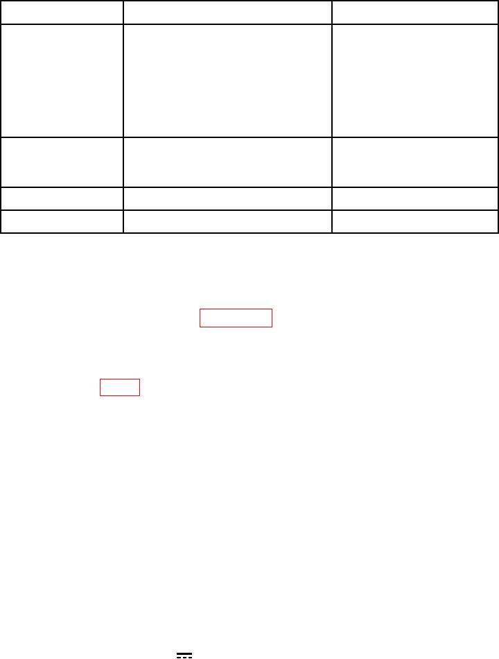
Table 2. Minimum Specifications of Equipment Required.
Manufacturer and model
Common name
Minimum use specifications
(part number)
Fluke, Model 5720A (5720A) (p/o
CALIBRATOR
DC voltage:
Range: 0 to 300 V
Accuracy: 0.05%
MIS-35947); w/ amplifier, Fluke
5725A/AR (5725A/AR)
AC voltage:
Range: 0 to 500 V
Frequency: 0 Hz to 1 kHz
Accuracy: 0.5%
DC Current: Range:3.5 to 10 A
Accuracy: 0.2%
AC Current: Range: 10 A
Frequency: 45 Hz to 1 kHz
Accuracy: 0.5%
Agilent, Model 81150A (81150A)
FUNCTION
Range:
10 Hz to 20 kHz
Accuracy:
0.002%
Amplitude:
8 V peak
DC offset:
0 to 4 V
10 mΩ to 1,211,111.11 Ω
Range:
IET Labs, HARS-LX-9-0.001
(0.125% + 0.5 mΩ)
Accuracy:
STANDARD NO. 1
(HARS-LX-9-0.001)
1 MΩ to 40 MΩ in 1 MΩ steps
Range:
IET Labs, HRRS-Q-4-1M-10KV-RM
STANDARD NO. 2
Accuracy:
0. 125%
(HRRS-Q-4-1M-10KV-RM)
CALIBRATION PROCESS
6. Preliminary Instructions
a. The instructions outlined in paragraphs 6 and 7 are preparatory to the calibration
process. Personnel should become familiar with the entire bulletin before beginning the
calibration.
b. Items of equipment used in this procedure are referenced within the text by common
name as listed in table 2.
c. Unless otherwise specified, verify the result of each test and, whenever the test
requirement is not met, take corrective action before continuing with the calibration.
Adjustments required to calibrate the TI are included in this procedure. Additional
maintenance information is contained in the manufacturers' manuals for this TI.
d. Unless otherwise specified, all control and control settings refer to the TI.
7. Equipment Setup
HIGH VOLTAGE is used or exposed during the performance of
this calibration.
DEATH ON CONTACT may result if
personnel fail to observe safety precautions.
REDUCE
OUTPUT(S) to minimum after each step within the
performance check where applicable.
a. Remove protective cover as needed to make adjustments.
Replace cover after
completing the adjustments.
b. Set TI rotary switch to V
.