
TB 9-6625-111-24
(7) Press TI rotary switch button for 2 seconds to enter Duty Cycle function.
(8) Set function generator as indicated in (a) through (d) below. Place a 50-ohm
load at the TI input.
(a) Output: 3.40 V p-p.
(b) Dc offset: 1.70 V.
(c) Waveform: Triangle.
(d) Frequency: 100 Hz.
(9) TI will indicate between 36% and 64%. If TI does not indicate within limits
specified, perform b below.
(10)Set function generator output to minimum.
b. Adjustments. No adjustments can be made.
14. RPM
a. Performance Check
(1) Connect function generator to TI RPM+ and 10A inputs. Place a 50-ohm load at
the TI input.
(2) Set function generator and TI settings as indicated in first row of table 7.
(3) TI will indicate between 1196 and 1204 RPM. If TI does not indicate within
limits specified, perform b below.
(4) Repeat (2) and (3) above for function generator and TI settings and indications
perform b below.
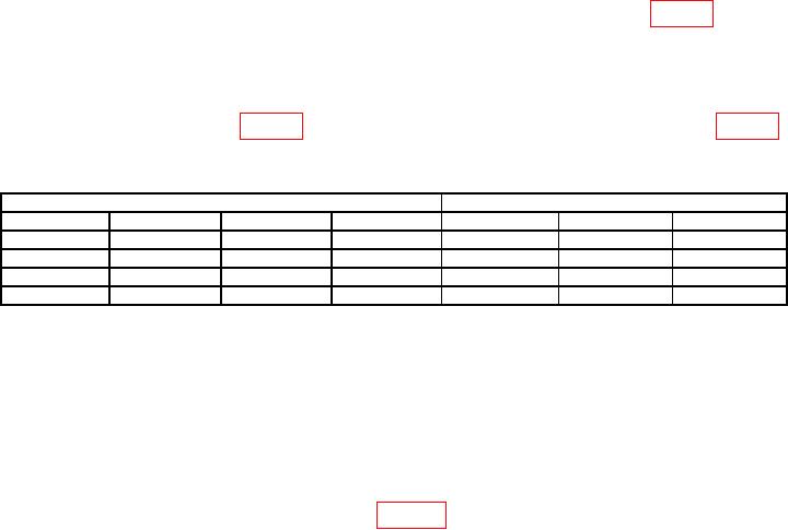
Table 7. RPM Accuracy.
Function Generator
Test Instrument
Output
Dc offset
Range
Min
Max
2.00 V p-p
1.70 V
Square
10 Hz
4V
1196 RPM
1204 RPM
2.00 V p-p
1.70 V
Square
10 Hz
40 V
0000 RPM
0000 RPM
2.00 V p-p
3.80 V
Square
10 Hz
40 V
1196 RPM
1204 RPM
2.00 V p-p
3.80 V
Square
10 Hz
4V
0000 RPM
0000 RPM
b. Adjustments. No adjustments can be made.
15. Temperature
a. Performance Check
NOTE
Characterize a length of type K thermocouple wire using the
technique in USATA 991.
(1) Connect equipment as shown in figure 1.
(2) Set TI function switch to C/F.