
TB 9-6625-1138-24
NOTE
Because of interaction, repeat (1) and (2) above until no further
adjustment is required.
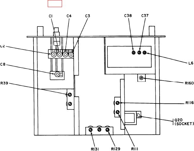
(3) Adjust R116 (fig. 1) for an indication of at least 1 V rms on multimeter (R).
Figure 1. Wave analyzer - adjustment locations.
9. Calibrator and Voltage Accuracy
a. Performance Check
(1) Position controls as listed in (a) through (c) below:
(a) MODE SELECTOR switch to NORMAL.
(b) RANGE switch to METER CAL.
(c) FREQUENCY dial adjusted for maximum TI R.M.S. VOLTS meter
indication (approx. 4 to 5 kHz).
(2) Adjust METER CAL adjustment screw (front panel) until TI R.M.S. VOLTS
meter indicates 1.0 on 0 to 1.0 scale. If 1.0 cannot be obtained, perform b (1) through (5) below.
(3) Connect calibrator to TI INPUT terminal.
(4) Set RANGE (VOLTS) switch to 1 V.