
TB 9-6625-1138-24
12. AFC Discriminator
a. Performance Check
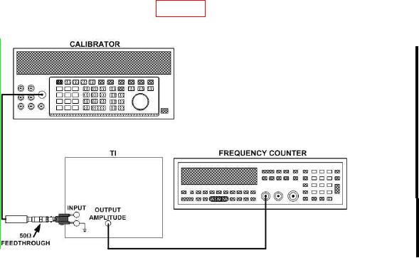
(1) Connect equipment as shown in figure 3.
Figure 3. AFC discriminator - equipment setup.
(2) Position controls as listed in (a) through (e) below:
RANGE (VOLTS) switch to 3 V.
(a)
MAX INPUT VOLTAGE switch to 3.
(b)
MODE SELECTOR switch to NORMAL.
(c)
SCALE VALUE switch to ABSOLUTE.
(d)
FREQUENCY dial to 400 Hz.
(e)
(3) Adjust calibrator output for 1 V and a 2.5 ms indication on counter.
(4) Position controls as listed in (a) through (e) below:
(a) RANGE (VOLTS) switch to 1 V.
(b) SCALE VALUE switch to RELATIVE.
(c) F R E Q U E N C Y d i a l t o s a m e f r e q u e n c y a s c a l i b r a t o r . F i n e - t u n e
p e a k indication.
(d) REF ADJUST control for 1 V.
(e) MODE SELECTOR switch to AFC.
NOTE
AFC circuit loss of control in (5) and (7) below is determined by
a sudden drop on TI R.M.S. VOLTS meter.
(5) Slowly increase calibrator frequency (AFC circuit will automatically track
changing frequency) until AFC circuit loses control. If counter indication is more than 2.0 ms,
perform b below.