
TB 9-6625-1138-24
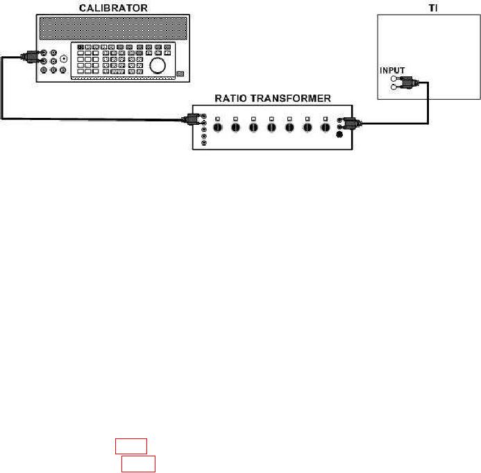
Figure 2. Calibrator and voltage accuracy - equipment setup.
(12) Set MAX INPUT VOLTAGE switch to .03 and RANGE (VOLTS) switch to 30
V.
(13) Adjust ratio transformer to indicate 0.0001.
(14) Adjust calibrator output until TI R.M.S. VOLTS meter indicates 3 on 0 to 3
scale. Calibrator will indicate between 0.285 to 0.315 Vrms.
(15) Set RANGE switch to 100 V.
(16) Adjust calibrator output until TI R.M.S. VOLTS meter indicates 1.0 on 0 to 1.0
scale. Calibrator will indicate between 0.95 and 1.05 Vac.
b. Adjustments
(1) Adjust calibrator for an output of 1.0 Vac.
(2) Set RANGE (VOLTS) switch to METER CAL.
(3) Adjust METER CAL adjustment screw until TI R.M.S. VOLTS meter indicates
1.0 to 1.0 scale.
(4) Adjust FREQUENCY dial for maximum indication on TI R.M.S. VOLTS meter
(approx. 4 to 5 kHz).
(5) Adjust R39 (fig. 1) until TI R.M.S. VOLTS meter indicates 1.0 on 0 to 1.0 scale (R).
(6) Adjust R111 (fig. 1) until oscilloscope indicates 7 V p-p (R).
10. Frequency Response
a. Performance Check
(1) Connect calibrator wideband output to TI INPUT terminal.
(2) Position controls as listed in (a) through (d) below:
MAX INPUT VOLTAGE switch to 1.
(a)
RANGE (VOLTS) switch to 100 mV.
(b)
SCALE VALUE switch to RELATIVE.
(c)
REF ADJUST control fully cw.
(d)
(3) Adjust calibrator output frequency for 400 Hz at an amplitude of 90 mV.