
TB 9-6625-1176-24
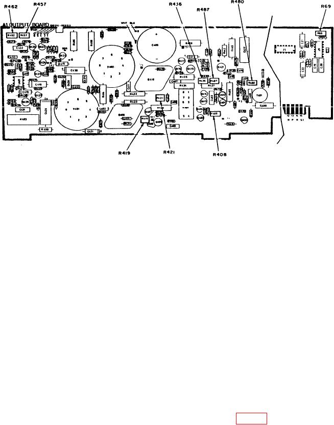
Figure 2. A1 (amplifier board) - adjustment locations.
(3) Measure time between TRIG OUTPUT and OUTPUT pulses, using standard
measurement technique. Frequency counter will indicate between 129 and 171 ns.
(4) Set PULSE POSITION VERNIER dial to 1. Frequency counter will indicate
between 48 and 72 ns.
(5) Disconnect OUTPUT from frequency counter and set DELAY/
ADVANCE/DOUBLE PULSE switch to ADVANCE. Connect TRIG OUTPUT to
oscilloscope CH 1 input. Connect OUTPUT to oscilloscope CH 2 input.
(6) Measure time between TRIG OUTPUT and OUTPUT pulses, using standard
measurement technique. The results will be between 28 and 52 ns.
(7) Set PULSE POSITION VERNIER dial to 10 and connect TI OUTPUT to
oscilloscope CH 2 and CH 3 inputs, using adapter (calibration fixture).
(8) Set oscilloscope trigger source to CH 3 and measure the time between OUTPUT
and TRIG OUTPUT pulses. Results will be between 29 and 71 ns.
(9) Disconnect cables from oscilloscope inputs and repeat (2) above.
(10)Position controls as listed in (a) through (d) below:
PERIOD l0m-.1 pushbutton pressed.
(a)
PERIOD VERNIER dial to 1.
(b)
PULSE POSITION .l -l pushbutton pressed.
(c)
DELAY/ADVANCE/DOUBLE PULSE switch to DELAY.
(d)
(11)Repeat technique of (3) above for settings listed in table 5. Indications will be
within specified limits.
8