
TB 9-6625-1176-24
(10) Repeat technique of (8) above. Oscilloscope display will disappear at a duty
cycle of 10 percent or greater (pulse width of 30 ns or greater).
(11) Position controls as listed in (a) through (e) below:
PERIOD 10m-. 1 pushbutton pressed.
(a)
AMPLITUDE 1-3 pushbutton pressed.
(b)
AMPLITUDE VERNIER dial to 3.
(c)
WIDTH 1 -10 pushbutton pressed.
(d)
WIDTH VERNIER dial to 1.
(e)
(12) Disconnect TI from oscilloscope and connect OUTPUT to frequency counter A
and B inputs, using adapter (calibration fixture).
(13) Measure pulse width, using standard measurement technique.
Frequency
counter will indicate between 0.8 and 1.205 s.
(14) Repeat technique of (13) above, using settings listed in table 6. Indications will
be within specified limits.
(15) Disconnect OUTPUT from frequency counter and connect to oscilloscope CH 1
input, using X10 attenuator.
(16) Connect TRIG OUTPUT to frequency counter A input and oscilloscope CH 2,
using adapter (calibration fixture) and 50 termination.
(17) Position controls as listed in (a) through (e) below:
PERIOD .1 -1 pushbutton pressed.
(a)
PERIOD VERNIER dial to 10.
(b)
PULSE POSITION VERNIER dial to 1.
(c)
DUTY CYCLE % pushbutton pressed.
(d)
INT LOAD pushbutton released (out).
(e)
(18) Set PERIOD VERNIER for exactly 1000 ns frequency counter indication.
Oscilloscope will display a pulse width of approximately 80 ns (8 percent duty cycle).
(19) Press PERIOD 1 -10 pushbutton and set PERIOD VERNIER for a 10,000 ns
frequency counter indication (2.5-10 percent duty cycle LED is illuminated).
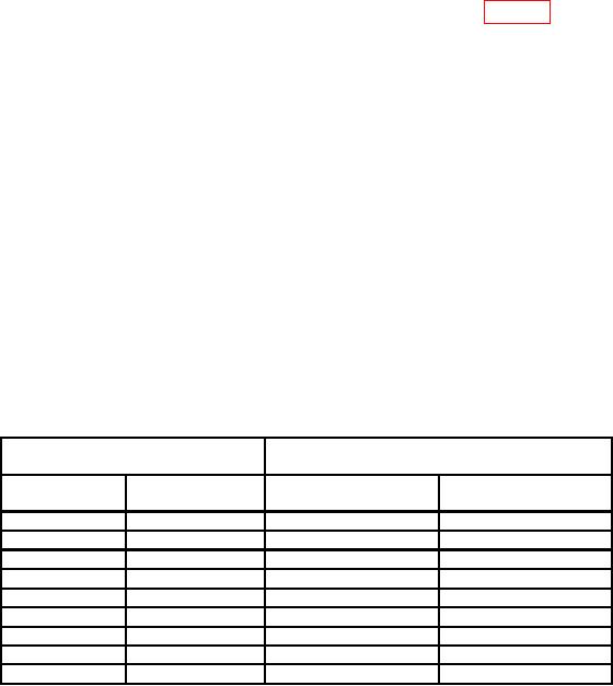
Table 6. Pulse Width
Frequency counter indications
( S)
Test instrument
WIDTH
VERNIER dial
Min
Max
pushbuttons
settings
1
8.00
12.00
10 - 0.1 m
0.1 m 1 m
1
80
120
1 m 10 m
1
800
1200
10
8.90
11.10
1 - 10
10
89.0
111.0
10 - 0.1 m
0.1 m 1 m
10
890
1110
1 m 10 m
10
8900
11100
1 m 10 m
9
8000
10000
1 m 10 m
8
7100
8900
11