
TB 9-6625-1176-24
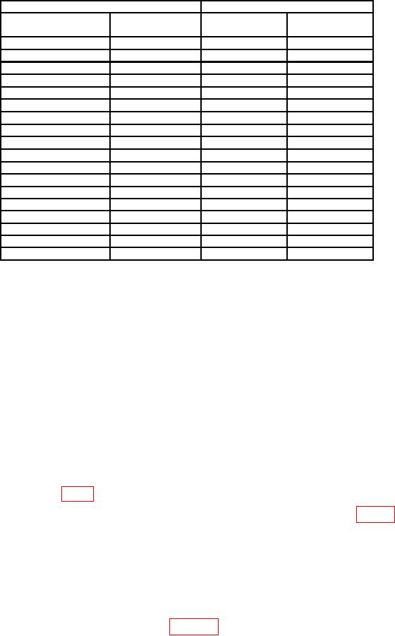
Table 5. Time Measurement for Delay Accuracy
Test instrument
Frequency counter indications
PULSE POSITION
VERNIER
pushbuttons
dial settings
Min
Max
0.1 -1
10
1.170 s
930
ns
1 -10
10
s
s
8.94
11.16
10 -0.1m
s
111.06 s
10
89.04
s
0.1 m-1 m
10
1.110 ms
890
1 m-10 m
10
8.900 ms
11.100 ms
0.1 -1
1
120
ns
180
ns
1
1.26 s
840 ns
1 - 10
8.04 s
12.06 s
1
10 - 0.1 m
80 s
120 s
0.1 m 1 m
1
800 s
1 m 10 m
1
1.200 ms
1 m 10 m
2
1.700 ms
2.300 ms
1 m 10 m
3
2.600 ms
3.400 ms
1 m - 10 m
4
3.500 ms
4.500 ms
1 m 10 m
5
4.400 ms
5.600 ms
1 m 10 m
6
5.300 ms
6.700 ms
1 m 10 m
7
6.200 ms
7.800 ms
1 m 10 m
8
7.100 ms
8.900 ms
1 m 10 m
9
8.000 ms
10.000 ms
b. Adjustments
(1) Position controls as listed in (a) through (i) below:
PERIOD 1m-10m pushbutton pressed.
(a)
PERIOD VERNIER dial to 10.
(b)
PULSE POSITION .1m-1m pushbutton pressed.
(c)
PULSE POSITION VERNIER dial to 10.
(d)
DUTY CYCLE % pushbutton released (out).
(e)
WIDTH 1 -10 pushbutton pressed.
(f)
WIDTH VERNIER dial to 10.
(g)
AMPLITUDE 3-10 pushbutton pressed.
(h)
DELAY/ADVANCE/DOUBLE PULSE switch to DELAY.
(i)
(2) Connect TRIG OUTPUT to frequency counter input, using 50
termination.
Connect OUTPUT to frequency counter B input.
(3) Adjust R45 (fig. 1) for a frequency counter indication between 990 and 1010 s (R).
(4) Set PULSE POSITION VERNIER dial to 1.
Adjust R119 (fig. 1) for a
frequency counter indication between 90 and 110 s (R).
(5) Set PULSE POSITION VERNIER dial to 10 and repeat (3) and (4) above for
best in-tolerance condition.
10. Pulse Width and Duty Cycle
a. Performance Check
(1) Connect equipment as shown in figure 3.