
TB 9-6625-1176-24
(21) Press AMPLITUDE .3-1 pushbutton and adjust C514 (fig. 1) for minimum
ringing (R).
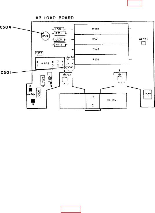
Figure 5. A3 (load board) - adjustment locations.
12. Trigger Output and Double Pulse
a. Performance Check
(1) Position controls as listed in (a) through (g) below:
PERIOD .1 -1 pushbutton pressed.
(a)
PERIOD VERNIER dial to 2.
(b)
PULSE POSITION 10n-.1 pushbutton pressed.
(c)
PULSE POSITION VERNIER dial to 1.
(d)
AMPLITUDE 3-10 pushbutton pressed.
(e)
AMPLITUDE VERNIER dial to 3.
(f)
INT LOAD pushbutton released (out).
(g)
(2) Connect TRIG OUTPUT to oscilloscope CH 1 input, using 50
termination.
Oscilloscope will display a pulse amplitude greater than 2.5 V and a pulse width of 10 ns.
(3) Connect equipment shown in figure 3.
(4) Position controls as listed in (a) through (h) below:
PERIOD VERNIER dial to 5.
(a)
PULSE POSITION .1 -1 pushbutton pressed.
(b)
PULSE POSITION VERNIER dial to 2.
(c)
WIDTH 25n-.1 pushbutton pressed.
(d)
WIDTH VERNIER dial to 2.
(e)
AMPLITUDE 30-100 pushbutton pressed.
(f)
AMPLITUDE VERNIER dial to 5.
(g)