
TB 9-6625-121-24
(4) Set Calibrator OPR/STBY switch to STBY.
(5) Move test lead from TI mA terminal to the A terminal.
(6) Set calibrator output for 900 mA. TI will indicate between 0.896 and 0.904 mA dc.
b. Adjustments. No adjustments can be made.
11. Ac Current
a. Performance Check
(1) Connect calibrator to TI A and COM inputs.
(2) To access A~, press TI blue button.
(3) Set calibrator output for 900 mA ac at 45 Hz. TI will indicate between 0.889 and
0.911 mA.
(4) Repeat (3) above for calibrator frequency settings of 400 Hz, 1 kHz and 2 kHz.
TI will indicate between 0.889 and 0.911 mA ac.
b. Adjustments. No adjustments can be made.
12. Dc Current Output
a. Performance Check
(1) Connect TI SOURCE A (+) and mA (-) outputs to multimeter and set
multimeter to read amps dc.
(2) Set TI rotary switch to the OUTPUT DC mA position.
(3) Set TI display, using the pushbuttons % STEP ▲ or ▼, to the first value listed
in the Span column of table 5 below. If TI does not indicate within limits specified in first
row of table 5, perform b below.
(4) Repeat (3) above for remaining values and indications in table 5 below.
If
indications are not within limits specified, perform b below.
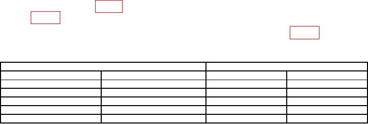
Table 5. Dc Current Source Accuracy.
Test instrument
Multimeter
Span
mA dc applied
Min
Max
0
%
4.000
3.99
4.01
25
%
8.000
7.99
8.01
50
%
12.000
11.99
12.01
75
%
16.000
15.99
16.01
100
%
20.000
19.99
20.01
b. Adjustments. No adjustments can be made.