TB 9-6625-1356-24
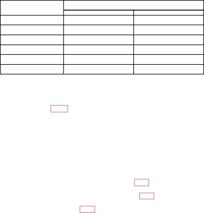
Table 9. Attenuator Accuracy
Test instrument
Attenuator value limits
(dB)1
OUTPUT ATTENUATOR
switch settings (dBm)
Min
Max
+10
9.90
10.10
(9.92)
(10.08)
0
19.90
20.10
(19.92)
(20.08)
-10
29.90
30.10
(29.92)
(30.08)
-20
39.90
40.10
(39.92)
(40.08)
-30
49.90
50.10
(49.92)
(50.08)
-40
59.90
(60.10
(59.92)
(60.08)
1Values
in parenthesis apply to Model 651B and 652A.
(16) Repeat (13) above for 40 dB. Designate this value as b.
(17) Repeat (15) above.
(18) Repeat technique of (16) and (17) above for each OUTPUT ATTENUATOR
switch setting listed in table 9. Attenuation value will be within limits specified.
NOTE
Value a will remain the same for each check.
b. Adjustments. No adjustments can be made.
14. Power Supply
a. Performance Check
NOTE
Do not perform power supply check if all other parameters are
within tolerance.
(1) Connect multimeter to CONNECTOR POINT 1 (fig. 1) and chassis ground. If
multimeter does not indicate between 29.1 and 30.9 V, perform b below.
(2) Connect multimeter to CONNECTOR POINT 2 (fig. 1) and chassis ground.
Multimeter will indicate between -24.25 and -25.75 V.
b. Adjustments. Adjust A1R4 (fig. 1) for a 30 V indication on multimeter (R).
15. Final Procedure
a. Deenergize and disconnect all equipment.
b. Annotate and affix DA label/form in accordance with TB 750-25.
15/(16 blank)

