
TB 9-6625-152-24
(3) Repeat technique of (1) (c) and (2) above for remaining TI carrier frequencies in
below.
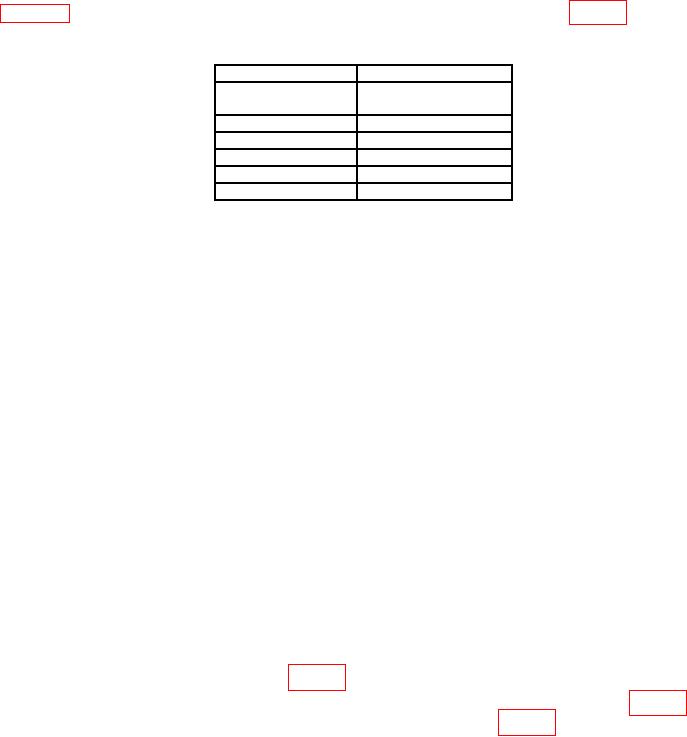
Table 8. Phase Noise.
Test instrument
Measuring receiver
Carrier frequency
Indication limit
(MHz)
(dBc/Hz)
1000
<-108
750
<-108
500
<-108
250
<-108
100
<-108
(4) Set TI output to minimum.
b. Adjustments. None.
13. Amplitude Modulation
a. Performance Check
(1) Set TI as listed in (a) through (g) below:
(a) Press Rx TEST key then [RF Gen].
(b) Press FREQ and set to 10 MHz.
(c) Press LEVEL and set to 0 dBm.
(d) Press Rx TEST, [Mod Gen], [Gen1/Gen2] until MOD1 FREQ is
highlighted, then press ON OFF key to off.
(e) Press Rx TEST, [Mod Gen], [Gen1/Gen2] until MOD2 FREQ is
highlighted, LEVEL, and set to 50%.
(f) Press Rx TEST, [Mod Gen], [Gen1/Gen2] until MOD2 FREQ is
highlighted, FREQ, and set to 1 kHz.
(g) Press Rx TEST, [Mod Gen], [Gen1/Gen2] until MOD2 FREQ is
highlighted, then press ON OFF key to on.
(2) Configure measuring receiver for AM depth measurement with Peak+ detector,
300 Hz high pass filter and 15 kHz low pass filter. If measuring receiver indication is not
within limits specified in first row of table 9, perform b below.
(3) Repeat technique of (1) (a), (b) and (2) for remaining TI frequencies in table 9. If
measuring receiver indications are not within limits specified in table 9, perform b below.