TB 9-6625-160-24
9. AC Level Accuracy and Output Level Accuracy and Flatness (8903B)
a. Performance Check
NOTE
The TI may display an ERROR code during this portion of the
Calibration Process. It can be disregarded and will clear when
the next set of Source values or Special Function is entered.
(1) Press TI numerical key for 41.0 and then SPCL key to initialize TI.
NOTE
For 8903B (S/N below 2742), use the impedance switch to set
the proper impedance. For 8903B only (S/N 2742 and above),
47.0 SPCL sets impedance to 600 Ω and 47.1 SPCL sets
impedance to 50 Ω. Verify the IMPEDANCE light is either on
or off for 50 Ω or 600 Ω respectively.
(2) Set TI SOURCE IMPEDANCE to 50 Ω (47.1 SPCL). Set 80 kHz LOW PASS
FILTER to off (Led off). Set INPUT and OUTPUT float switches to ground.
(3) Connect CALIBRATOR OUTPUT to TI INPUT HIGH connector.
(4) Press TI numeric keys for first special function listed in table 7 below and then
press SPCL key.
(5) Ensure TI RATIO button is off (Led off).
(6) Set TI numeric keys for first value listed in ratio column of table 7 below.
NOTE
Key in ratio numeric value only. DO NOT press the V or mV key.
(7) Set TI RATIO button to on (LED on).
(8) Set CALIBRATOR controls to first values listed in level and frequency columns
of table 7.
(9) Set CALIBRATOR OPR/STBY switch to OPR.
(10) Record TI right display indication for use in steps (21) and (31) below. TI must
indicate within corresponding limits specified in table 7 below.
(11) Repeat technique of (4) through (10) above for remaining parameters and limits
listed in table 7 below.
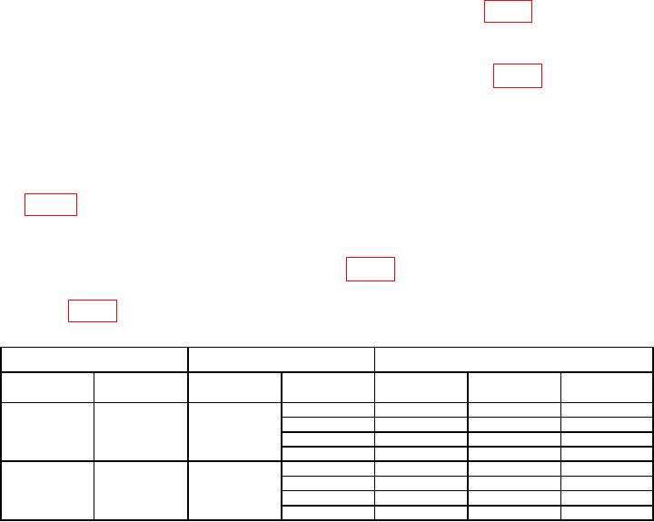
Table 7. AC Level Accuracy and Flatness (HIGH INPUT).
TI
Calibrator
TI Limits Ratio (%)
Special
Ratio1
Level (V rms)
Min
Indicated (%)
Max
function
(Hz)
1.1
300
300
40
98
102
1k
98
102
20 k
98
102
100 k
96
104
1.2
150
150
100 k
96
104
20 k
98
102
1k
98
102
20
98
102
See footnotes at end of table.

