TB 9-6625-160-24
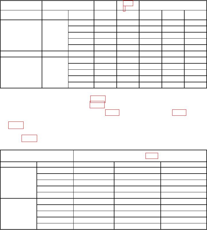
Table 5. Output Level Accuracy and Flatness.
TI Right
TI
TI Source
Limits (mVrms)
display
3 or 4
Level
Special Function
Step (21)
%
Min
Actual
Max
(V)
(Hz)
1.11
6
20
5880
6120
1k1
5880
6120
20 k
5880
6120
50 k
5880
6120
100 k
5880
6120
1.16
0.6
1k
588
612
1.19
0.0006
20
0.57
0.63
1k1
0.57
0.63
20 k
0.57
0.63
50 k
0.57
0.63
100 k
0.57
0.63
1000 Hz Recorded REF.
1
(23) Calculate source flatness in table 6 below by subtracting 1000 Hz recorded REF
Difference % = value recorded in table -
Hz recorded REF table
from listed frequency value recorded in table 5 above, as shown below:
(24) Calculated source flatness (mV), must be within corresponding limits specified
in table 6 below.
(25) Repeat technique of (23) and (24) above for remaining parameters and limits
listed in table 6 below.
Table 6. Source Flatness.
Source
Values from table 5
(V)
(Hz)
Actual
1000 Hz REF
Difference limits (mV)
6
1k
REFERENCE
20
42
20 k
42
50 k
150
100 k
150
0.0006
1k
REFERENCE
20
0.0042
20 k
0.0042
50 k
0.0150
100 k
0.0150
b. Adjustments
(1) Remove top cover of TI; A2 board is located towards front of TI.
(2) Press TI numerical key for 41.0 and then SPCL key to initialize TI. Set INPUT
switch to ground. Set LP FILTER off. Key in 1.10 SPCL to set input to 4.76 V range.
(3) Set CALIBRATOR for 4.5 V rms at 1 kHz and connect CALIBRATOR to TI
HIGH INPUT.
9

