
TB 9-6625-168-24
Table 5. Forward Power Indication.
Signal generator
RF power meter
Test instrument
1
Output
Indication
Indication limits
(W)
Frequency (MHz)
Level (dBm)
Min (W)
Max (W)
30
0
1.0
0.8
1.2
30
0
3.0
2.4
3.6
30
0
30
24
36
30
0
50
40
60
1
60
0
1.0
0.8
1.2
60
0
3.0
2.4
3.6
60
0
30
24
36
60
0
50
40
60
1
88
0
1.0
0.8
1.2
88
0
3.0
2.4
3.6
88
0
30
24
36
88
0
50
40
60
Before changing frequencies set signal generator output off and RF amplifier output control to minimum.
1
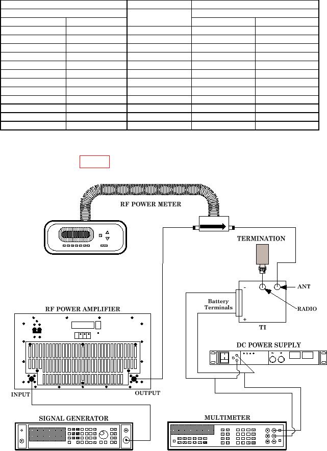
(12) Set signal generator and RF power amplifier outputs to minimum and connect
equipment as shown in figure 3 below.
Figure 3. Reverse Power Connection.
7