
TB 9-6625-168-24
CAUTION
Due to the possibility of RF power amplifier spikes which may
cause equipment damage, reduce signal generator and RF
amplifier outputs to minimum when signal generator output
frequency is changed in the steps below.
(13) Set signal generator for an output frequency of 30 MHz @ 0 dBm.
(14) Slowly increase RF power amplifier for an RF power meter indication of 1 W. TI
RVS power indication must be within limits specified in first row of table 6.
(15) Repeat technique of (13) and (14) above for remaining signal generator outputs
and RF power meter indications listed in table 6. TI RVS power indication must be within
limits specified in table 6.
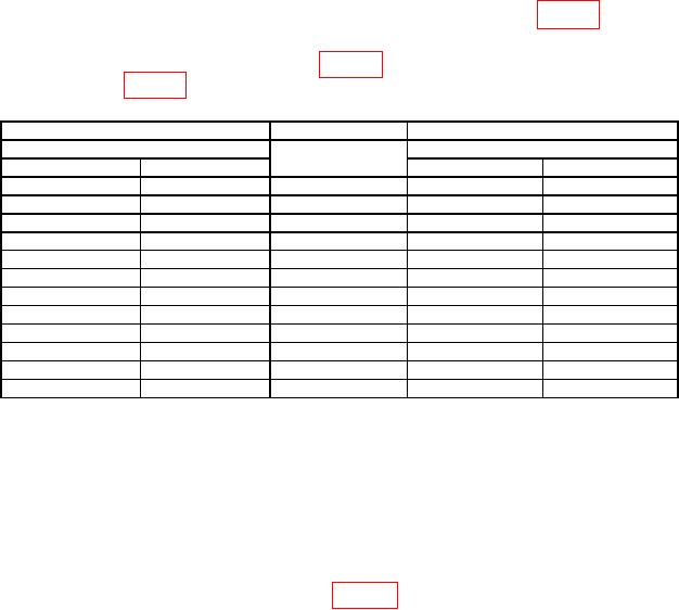
Table 6. Reverse Power Indication.
Signal generator
RF power meter
Test instrument
1
Output
Indication
Indication limits
(W)
Frequency (MHz)
Level (dBm)
Min (W)
Max (W)
30
0
1.0
0.8
1.2
30
0
3.0
2.4
3.6
30
0
30
24
36
30
0
50
40
60
1
60
0
1.0
0.8
1.2
60
0
3.0
2.4
3.6
60
0
30
24
36
60
0
50
40
60
1
88
0
1.0
0.8
1.2
88
0
3.0
2.4
3.6
88
0
30
24
36
88
0
50
40
60
Before changing frequencies set signal generator output off and RF amplifier output control to minimum.
1
(16) Set all outputs to minimum and disconnect equipment setup.
b. Adjustments. None.
9. Receiver Test (TI Transmitting)
a. Performance Check
(1) Connect equipment as shown in figure 4 below.
NOTE
TI will automatically turn off after 120 seconds. Press and hold
button to keep TI on.
(2) Configure multimeter for DC Volts measurement and set DC power supply
output for a 5.5 V dc multimeter indication.
(3) Configure measuring receiver for spectrum analysis mode.
(4) Adjust measuring receiver spectrum analyzer as required to observe frequencies
from 30 to 85 MHz in 5 MHz intervals. Output levels will indicate between -95 and
-101 dBm from 30 to 85 MHz.