
TB 9-6625-1914-24
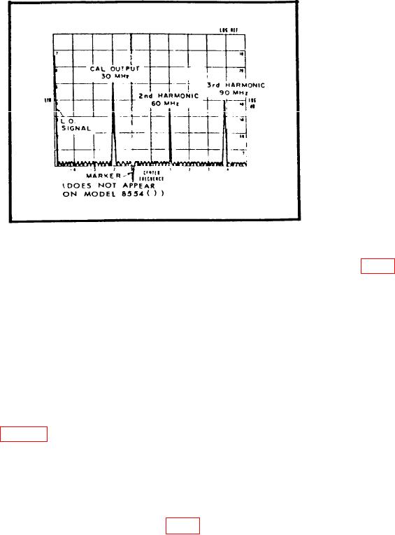
Figure 1. 30 MHz calibration signal and harmonics.
(5) FREQUENCY control adjusted to center CAL OUTPUT 30 MHz marker (fig. 1)
on display.
NOTE
Use RF plug-in FREQUENCY FINE TUNE control to keep
CAL OUTPUT 30 MHz marker centered on display.
n. Set LOG REF LEVEL switch until displayed signal amplitude is exactly on -70 dB
graticule line.
NOTE
LOG and LIN scales are not on some display sections. If not,
use figure 1 as guideline.
o. Rotate LOG REF LEVEL switch seven steps cw. If displayed signal amplitude
does not increase in increments of one division per 10 dB step, perform p and q below. If
signal amplitude is proper, perform r below.
p. Adjust DISPLAY ADJUST VERTICAL GAIN control to position signal amplitude
display exactly on LOG REF (top) graticule line (fig. 1).
q. Repeat m through o above as necessary to obtain optimum adjustment of DISPLAY
ADJUST VERTICAL GAIN control.
r. Position TI controls as listed in (1) and (2) below:
(1) LOG/LINEAR switch to LINEAR.
9