
TB 9-6625-1914-24
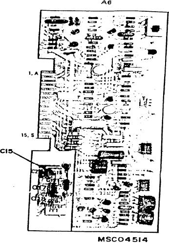
Figure 4. Test instrument - board A6 adjustment locations.
10. Bandwidth Accuracy
a. Performance Check
(1) Position RF plug-in controls as listed in (a) through (g) below:
(a) RANGE MHz switch (Model 8553B only) to 0-110.
(b) FREQUENCY control to 30 MHz.
(c) BANDWIDTH switch to 100 kHz.
(d) SCAN WIDTH (red) switch to PER DIVISION.
(e) SCAN WIDTH PER DIVISION switch to 0.05 MHz (50 kHz on Model 8554B).
(f) INPUT ATTENUATION switch to 10 dB.
(g) TUNING STABILIZER switch to ON (up).