
TB 9-6625-1932-24
c. Evaluate TI for frequency range and determine cardinal test point frequencies from
standard thermistor mount chart selected in b above.
d. Set power meter No. 1 CALIBRATION FACTOR control to 100% and standardize TI.
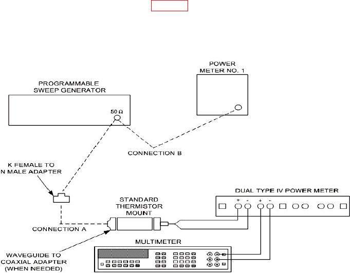
e. Connect equipment as shown in figure 2.
f. Energize equipment and allow 1 hour for warm-up.
g. Prepare a test report for all thermistor mounts certified for system codes U10, U11,
and U12.
Figure 2. Thermistor mount/power sensor (10 to 40 GHz) - equipment setup.
8. Power Accuracy
a. Performance Check
cardinal test point frequency determined in 7 c above.
NOTE
Perform (2) below for TI power sensors or (3) below for TI
thermistor mounts.