
TB 9-6625-1962-24
8. Dc Volts
a. Performance Check
(1) Connect lead between TI COM INPUT connector and ground post connector on
indicator oscilloscope.
(2) Connect calibrator OUTPUT V A HI and LO to TI INPUT HIGH and COM terminals.
(3) Set MODE/RANGE switch to DC VOLTS 2V.
(4) Adjust calibrator output to obtain indicator oscilloscope readout display of 2.000
volts. If calibrator does not indicate between 1.997 and 2.003 volts, perform b below.
(5) Adjust calibrator to obtain indicator oscilloscope readout display of -2.000 volts.
If calibrator does not indicate between -1.997 and -2.003 volts, perform b below.
(7) Repeat technique of (3) through (5) above for MODE/RANGE switch positions
listed in table 3. Calibrator indications will be within limits specified.
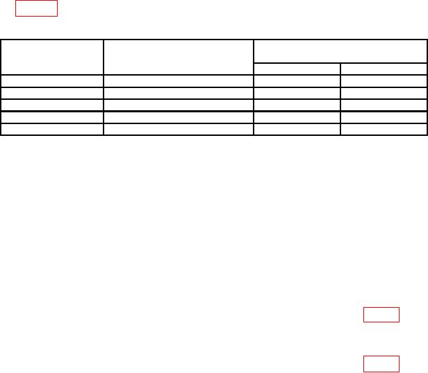
Table 3. Dc Volts
Indicator oscilloscope
Calibrator indications
Test instrument
MODE/RANGE
readout display
(V)
switch positions
indications
Min
Max
DC VOLTS 20V
2.000
1.99
2.01
DC VOLTS 20V
20.00
19.97
20.03
DC VOLTS 200V
20.00
19.9
20.1
DC VOLTS 200V
200.0
199.7
200.3
DC VOLTS 1kV
1000.0
998
1002
b. Adjustments
NOTE
For adjustments on model 7D13A, use calibration fixture
(extender) for access to adjustments.
(1) Adjust calibrator for 2.0000 volts.
(2) Connect frequency counter between TP206 (located near center of circuit board
assembly) and ground. If frequency counter does not indicate between 79.5 and 80.5 kHz,
adjust R203 (located adjacent to TP206) to obtain an indication of 80 kHz. Remove
frequency counter connection.
(3) Adjust R148 GAIN ADJ (7D13) R1003 VOLTS (7D13A) (fig. 1) to obtain
indicator oscilloscope readout display of 2.000 volts (R).
(4) Adjust calibrator for -2.0000 volts.
(5) Adjust R148 GAIN ADJ (7D13) R1003 VOLTS (7D13A) (fig. 1) to obtain
indicator oscilloscope readout display of -2.000 volts.
(6) Repeat (1) and (3) through (5) above for best compromise between positive and
negative 2.000 volts.