
TB 9-6625-1962-24
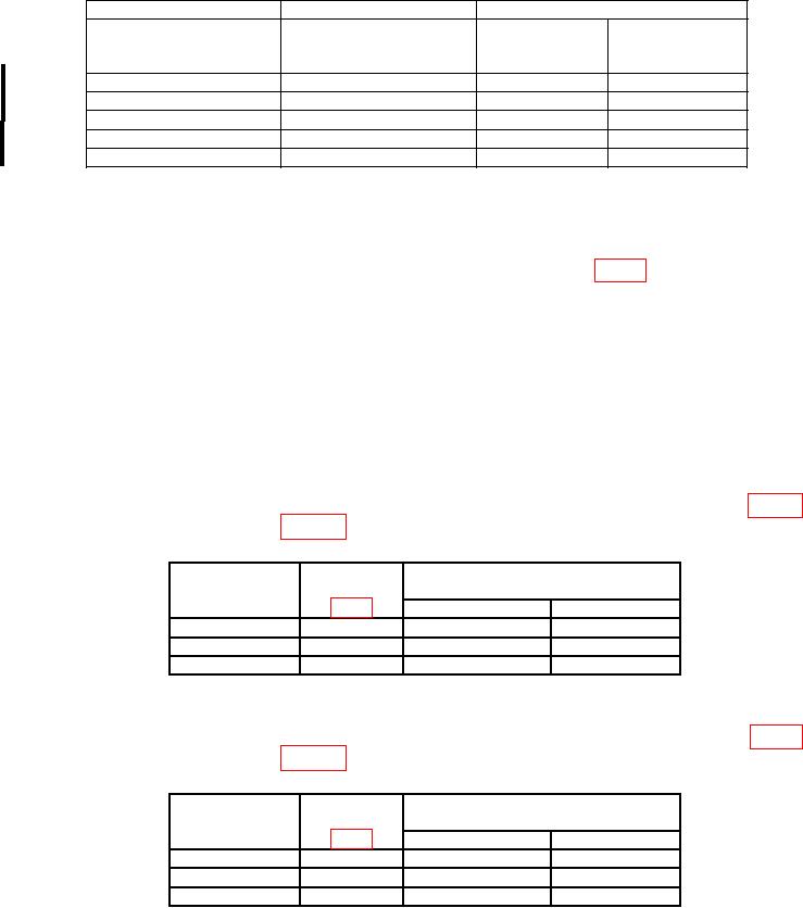
Table 5. Resistance - Continued
Test instrument
Indicator oscilloscope
Calibrator
err
Readout display
MODE/RANGE switch
Nominal output display indication
indications
( )
( )
(%)
positions
1900
1.900 k
1.00
RESISTANCE 20 k
19.00 k
19.00 k
1.00
RESISTANCE 200 k
190.0 k
190.0 k
0.55
RESISTANCE 200 k
190.0 k
190.0 k
1.00
RESISTANCE 2 M
1.900 M
1.900 M
0.55
RESISTANCE 2 M
b. Adjustments
(1) Set calibrator for 19.000 k ohms.
(2) Adjust R44 OHMS ADJ (7D13) R1005 OHMS (7D13A) (fig. 1) to obtain indicator
oscilloscope readout display of 19.00 k ohms (R).
11. Power Supply
a. Performance Check
NOTE
Do not perform power supply check if all other parameters are
within tolerance. Perform (1) below for model 7D13 and
perform (2) below for model 7D13A.
(1) Connect multimeter between floating power supply COMMON TP422 (fig. 1)
and each test point listed in table 6. Multimeter will indicate within limits specified.
Table 6. Power Supply (7D13)
Multimeter indications
Power supply
Test points
(V dc)
voltage (V dc)
Min
Max
+15
TP434
+14.1
+15.9
1
-15
TP439
-14.1
-15.9
TP4482
+5
+4.7
+5.3
1Q438
emitter in early production instruments.
2Q447
emitter in early production instruments.
and each test point listed in table 7. Multimeter will indicate within limits specified.
Table 7. Power Supply (7D13A)
Multimeter indications
Power supply
Test points
(V dc)
voltage (V dc)
Min
Max
+12
TP+12 VF
+11.28
+12.72
-12
TP-12 VF
-12.72
-11.28
+5
TP+5 VF
+4.7
+5.3
b. Adjustments. No adjustments can be made.
8 CHANGE 1