
TB 9-6625-1966-24
(4) Set oscilloscope coupling switch to GND and vertically center the baseline of
waveform on oscilloscope screen. Set coupling switch to DC. If oscilloscope display is not
vertically centered on graticule centerline within 200 mV, perform b (1) below.
(5) Repeat technique of (4) above with CHANNEL A function switch set to
TRIANGLE and then to SQUARE.
(6) Remove connection from CHANNEL A OUTPUT and connect to CHANNEL B
OUTPUT.
(7) Repeat (3) and (4) above for CHANNEL B AMPLITUDE. If oscilloscope
display is not vertically centered on graticule centerline within
200 mV,
p e r f o r m b ( 2 ) below.
(8) Repeat (4) and (7) above with CHANNEL B function switch set to TRIANGLE,
and then to SQUARE.
b. Adjustments
(1) Adjust A15R7 or A5R7 (fig. 2) for optimum centering of waveform on screen in
SQUARE, TRIANGLE, and SINE positions of CHANNEL A function switch (R).
(2) Adjust A16R7 or A6R7 (fig. 2) for optimum centering of waveform on screen in
SQUARE, TRIANGLE, and SINE positions of CHANNEL B function switch (R).
12. Maximum Output Voltage
a. Performance Check
(1) Connect oscilloscope to CHANNEL OUTPUT.
NOTE
If a substitute oscilloscope is used, it must have an input
impedance of 1 M or greater.
(2) Adjust CHANNEL A AMPLITUDE control fully ccw.
(3) Set CHANNEL A function switch to positions listed in table 4. Oscilloscope will
indicate within limits specified.
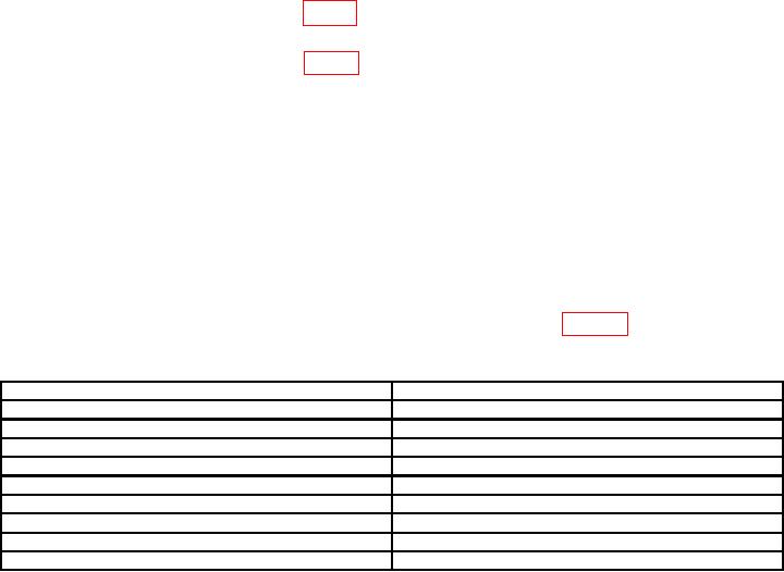
Table 4. Output Voltage
Test instrument function switch
Oscilloscope indications (V p-p)
SINE
>35
TRIANGLE
>35
SQUARE
>35
SQUARE1
>2
TRIANGLE
>2
SINE
>2
SINE2
>15
TRIANGLE
>15
SQUARE
>15
1Connect
50 load to TI OUTPUT, using decade resistor.
decade resistor to 600 .
2Adjust