
TB-9-6625-1968-24
indication of 10.2 MHz. This allows for the frequency shift when the cover is installed.
Wait 10 minutes and check frequency. If frequency counter does not indicate 10 MHz 100
kHz, repeat adjustment sequence (R).
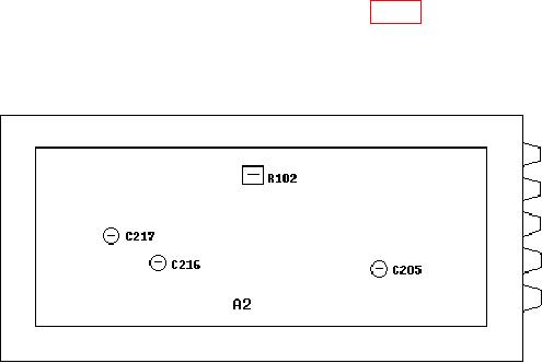
Figure 1. Test instrument - bottom view.
9. Sine Wave Distortion
a. Performance Check
(1) Connect TI Vp-p to audio analyzer INPUT HIGH using 50
feedthrough
termination.
(2) Position controls as listed in (a) through (d) below:
FUNCTION sine wave pushbutton pressed.
(a)
RANGE Hz 10 pushbutton pressed.
(b)
FREQUENCY dial to 2.
(c)
AMPLITUDE switch to 10 and AMPLITUDE VERNIER control centered.
(d)
(3) Set audio analyzer to measure distortion in percent. If audio analyzer does not
indicate <0.5 percent, perform 9 b (1) and (2) below.
(4) Press RANGE Hz 100 pushbutton, adjust FREQUENCY dial to 10, and repeat
(3) above.
(5) Press RANGE Hz 1k pushbutton and repeat (3) above.
(6) Press RANGE Hz 10k pushbutton, adjust FREQUENCY dial to 5, and repeat
(3) above.
(7) Disconnect audio analyzer and 50
feedthrough termination from TI.
(8) Connect audio analyzer INPUT HIGH to TI MOD INT-EXT.
(9) Press MODULATION sine wave pushbutton.
(10) Set audio analyzer to measure frequency.