
TB 9-6625-1976-24
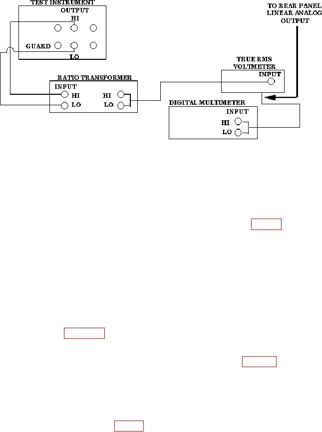
Figure 2. 1 mVAC equipment setup.
(11) Press true rms voltmeter FUNCTION pushbutton to FILT IN.
(12) Set multimeter for dc voltage measurement.
(13) Set SENSE switch to INT and MODE switch to OPER.
(14) Set ratio transformer dials to .1000000.
(15) Set TI VOLTAGE dials to the setting recorded in step 16 of table 6.
(16) Establish upper and lower limits for 1 mV range by:
(a) Upper limit - Set ratio transformer dials to .0010102. Record multimeter
indication.
(b) Lower limit - Set ratio transformer dials to .0009898. Record multimeter
indication.
(17) Set ratio transformer dials to 1.0000000.
(18) Set TI VOLTAGE RANGE switch to 1 mV and VOLTAGE dials to
1.00000 mV. Multimeter indication will be within limits recorded in (16) above.
b. Adjustments (Figure 1)
NOTE
Adjustments sequenced together (as indicated in table 6)
interact with each other and should be adjusted until
indications converge.
(1) Adjust A8R63 for best null indication on multimeter (R).
(2) Adjust A12R48 for best null indication on multimeter (R).
(3) Repeat steps 1 and 2 of table 6 and b (1) and (2) above, as necessary, until both
indications are within limits.
(4) Adjust A6R9 for best null indication on multimeter (R).
13