
TB 9-6625-1979-24
(4) Set HI/LO LINE VOLTAGE selector switch to LO. Vary autotransformer
output between 90 and 118 V ac while observing that voltage is still within tolerance.
Adjust autotransformer for 115 V output.
(5) Set HI/LO LINE VOLTAGE selector switch to HI.
(6) Connect multimeter across test load unit -15 V terminals.
Multimeter will
indicate between -14.77 and -15.23 V dc.
(7) Connect multimeter across test load unit +5 V terminals.
Multimeter will
indicate between +4.9 and +5.1 V dc.
(8) Repeat (2) through (5) above for test load unit +5 V terminals.
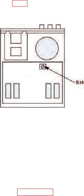
b. Adjustments. Adjust R16 (fig. 1) until multimeter indicates +15 V dc (R). It may
be necessary to readjust R16 for best compromise of +15, -15, and +5 V supplies.
Figure 1. Power Supply - top view.
9. Final Procedure
a. Deenergize and disconnect all equipment.
b. Annotate and affix DA label/form in accordance with TB 750-25.
CALIBRATION PROCESS FOR PROBE,
TEKTRONIX, TYPE P6201
10. Preliminary Instructions
a. The instructions outlined in paragraphs 10 and 11 are preparatory to the calibration
process. Personnel should become familiar with the entire bulletin before beginning the