
TB 9-6625-1979-24
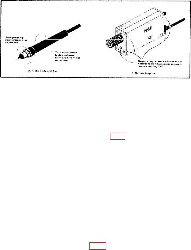
Figure 3. Probe body and output amplifier access methods.
(12) Set oscilloscope vertical 1 input to DC input coupling, 1M
input impedance
and vertical scale for maximum sensitivity.
(13) Connect TI probe tip to oscilloscope ground terminal and set oscilloscope for a
free running trace. Position the trace to graticule center.
(14) Remove TI probe tip from oscilloscope ground terminal. If oscilloscope trace is
not positioned on the center graticule, perform b (4) below.
(15) Connect multimeter to the base of Q300 (fig. 2) and ground. If multimeter does
not indicate between -3.275 and -3.325, perform b (5) below.
(16) Disconnect multimeter and temporarily reinstall the two housing halves on the
TI output amplifier. Allow 20 minute warm-up with housings reinstalled.
(17) Remove the housing halves and repeat (15) and (16) above.
(18) Connect TI output amplifier to the input of oscilloscope and probe to output of
function generator.
(19) Set 50
TERM switch to EXT.
(20) Set oscilloscope vertical scale to 20 mV and sweep time to 5 ns. Adjust function
generator for a 5 division display on oscilloscope.
(21) Locate a glitch approximately 20 ns from the positive step of the waveform.
(This glitch represents the probe's cable length x 2.)
(22) For serial number B076840 and up only, adjust C160 for minimum glitch.
(23) Disconnect the probe tip and adapter and reassemble outer probe body.
b. Adjustments
(1) Adjust R250 OUTPUT ZERO (fig. 2) until trace is centered vertically on
oscilloscope.
8