
TB 9-6625-2043-24
to-one ratio between the standard and TI. Where the four-to-one ratio cannot be met, the
actual accuracy of the equipment selected is shown in parenthesis.
5. Accessories Required. The accessories required for this calibration are common
usage accessories issued as indicated in paragraph 4 above and are not listed in this
calibration procedure.
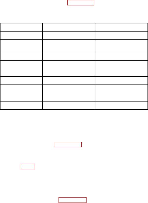
Table 2. Minimum Specifications of Equipment Required
Manufacturer and model
Common name
Minimum use specifications
(part number)
FREQUENCY
Range: 10 to 11 ms
Fluke, Model PM6681/656
0.1%
COUNTER
(PM6681/656)
Accuracy:
FUNCTION/
Frequency: 200 kHz
Agilent, Model 33250A
ARBITRARY
Amplitude: 0.1 mV to
(33250A)
1.0 V
Range: 1 to 16 V dc
Fluke, Model 8840A/AF05
0.1%
(AN/GSM-64D)
Accuracy:
POWER METER
Range: -10 to 0 dBm
Agilent, Model E12-432A (MIS-
5%
30525) w/thermistor mount,
Accuracy:
Agilent, Model 478A- H75-
(7915907) or 8478B (8478B)
POWER SPLITTER
Range: 1 to 12 GHz
Weinschel, Model 1870A
(7916839)
SYNTHESIZED
Range: 1 to 12 GHz
Anritsu, Model 68369NV
1%
SIGNAL GENERATOR
(68369NV)
Accuracy:
Amplitude: +13 dBm
minimum
TRUE RMS
Frequency: 200 kHz
Fluke, Model 8922A/AA
0.02% ( 0.5%)
(8922A/AA)
Accuracy:
CALIBRATION PROCESS
6. Preliminary Instructions
a. The instructions outlined in paragraphs 6 and 7 are preparatory to the calibration
process. Personnel should become familiar with the entire bulletin before beginning the
calibration.
b. Items of equipment used in this procedure are referenced within the text by common
name as listed in table 2.
c. Unless otherwise specified, verify the result of each test and, whenever the test
requirement is not met, take corrective action before continuing with the calibration.
Adjustments required to calibrate the TI are included in this procedure. Additional
maintenance information is contained in the manufacturers' manuals and TM 11-6625-2857-14 for
this TI.
d. When indications specified in paragraphs 8 through 14 are not within tolerance,
perform the power supply check prior to making adjustments. After adjustments are made,