
TB 9-6625-2050-35
(9) Set range calibrator RANGE switch to -10 dBm.
(10) Press TI MODE pushbutton to dB (REF).
TI digital readout will indicate
between -0.01 and +0.01.
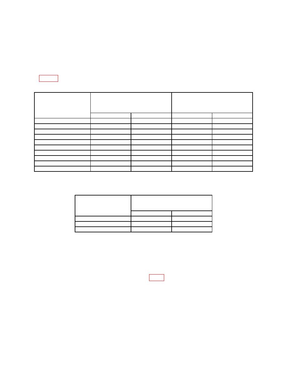
(11) Set range calibrator RANGE switch and TI RANGE switches to settings listed
in table 8. If TI does not indicate within limits specified, perform b below.
Range calibrator switch
settings and test
Multimeter indications
Test instrument digital display
instrument meter
(V dc)
indications
RANGE
indications
Min
Max
Min
Max
10 W
W
10.05 W
0.995
1.005
9.95
100 W
W
W
0.995
1.005
99.5
100.5
1 mW
0.995 mW
1.005 mW
0.995
1.005
10 mW
9.95
mW
10.05 mW
0.995
1.005
100 mW
99.5
mW
100.5
mW
0.995
1.005
-20 dBm
-20.02
dBm
-19.98 dBm
0.995
1.005
1
-10 dBm
-10.02
dBm
-9.98 dBm
0.995
1.005
0 dBm
-0.02
dBm
0.02 dBm
0.995
1.005
+10 dBm
9.98
dBm
10.02 dBm
0.995
1.005
+20 dBm
19.98
dBm
20.02 dBm
0.995
1.005
1Press
TI MODE dBm pushbutton.
(Models 436A and 436AOPT9/22)
Test instrument meter
Range calibrator switch
RANGE indications
settings
(dB (REL))
(dBm)
Min
Max
-20
-9.96
-10.04
-5
+4.96
+5.04
+10 dBm
+19.96
20.04
b. Adjustments
(1) Press TI LINE pushbutton to OFF (out) and MODE pushbutton to WATT.
(2) Set range calibrator FUNCTION switch to CALIBRATE and POLARITY
switch to NORMAL.
(3) Connect frequency counter to A2TP5 (fig. 1).
NOTE
PC extender board and rubber bumpers should be installed to
extender board to prevent board from touching.
(4) Press TI LINE pushbutton to ON (in).
