
TB 9-6625-2050-35
(4) Reposition power reference oscillator on power meter chassis but do not replace
mounting screws.
(5) Observe indication on the counter. If it is 50.0 MHz, the adjustment procedure
is complete. If it is not within these limits, repeat b (3) except offset power reference
oscillator frequency as required to obtain a 50.0 MHz indication on counter when power
reference oscillator assembly is repositioned on power meter chassis.
a. Performance Check
(1) With power meter off, remove thermistor mount from interconnect cable. Adjust
power meter and pin 1 on thermistor mount end of power meter interconnect cable.
(2) Round off multimeter indication two decimal places and record this value as
internal bridge resistance R of power meter (approximately 200 Ω).
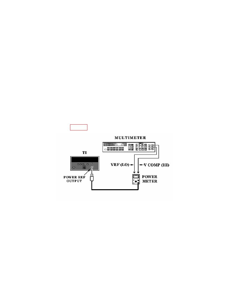
(3) Reconnect thermistor mount to power meter interconnect cable and connect
equipment as shown in figure 6.
(4) Press TI LINE pushbutton to ON and POWER REF pushbutton to off. Set
power meter switch to on and wait 30 minutes for thermistor mount to stabilize before
proceeding.
(5) Set power meter RANGE switch to COARSE ZERO and adjust front panel
COARSE ZERO control for a zero meter indication.
(6) Zero power meter on the most sensitive range, then set power meter RANGE
switch to 1 mW.
