
TB 9-6625-2077-24
(8) Verify that the audio analyzer indicates within the limits listed in table 3. If
audio analyzer does not indicate within the limits specified perform b below.
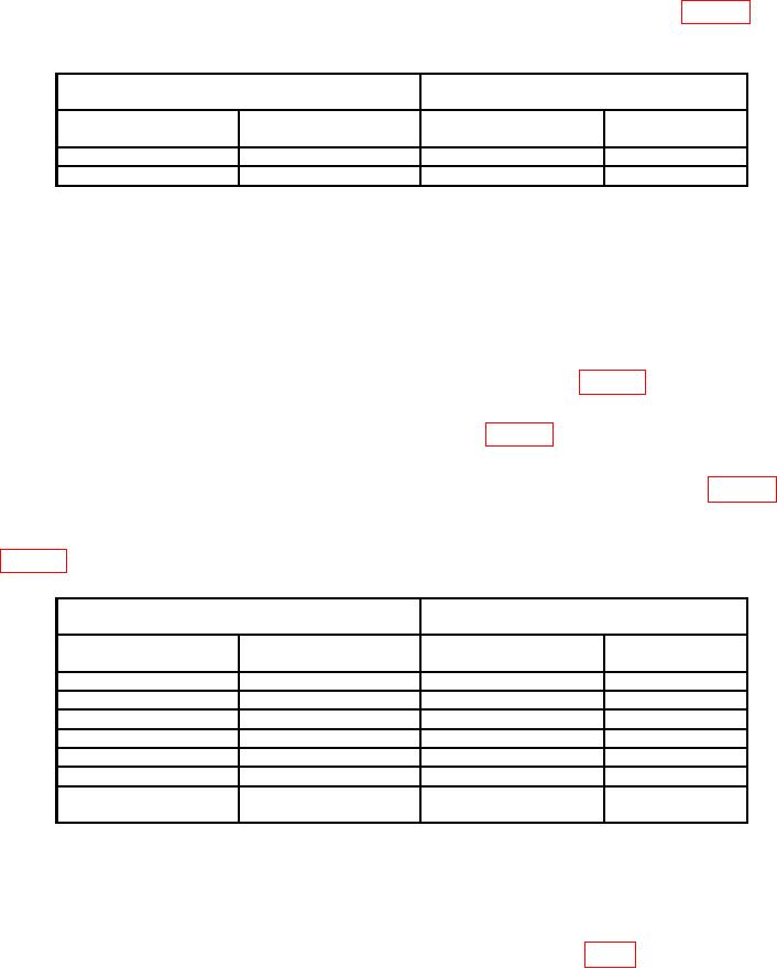
Table 3. Frequency Measurement Using Audio Analyzer
Audio analyzer indications
Test instrument
(kHz)
TUNING RANGE
control setting
display
Min
Max
50-250 kHz
50
kHz
49.500
50.500
50-250 kHz
100
kHz
99.000
101.000
(9) Disconnect TI from audio analyzer INPUT HIGH.
(10) Connect sensor module to the power reference output. Perform sensor zero and
(11) Connect measuring receiver sensor module to TI without the 50
feedthrough
termination.
(12) Set measuring receiver to the frequency counter mode.
(13) Set TUNING RANGE switch to the first setting listed in table 4.
(14) Adjust TUNING COARSE and FINE controls for a reading on the
FREQUENCY display that is equal to the value listed in table 4.
(15) Adjust RF OUTPUT LEVEL control for a 0 dBm indication on RF OUTPUT meter.
(16) Verify that the measuring receiver indicates within the limits listed in table 4.
If measuring receiver does not indicate within the limits specified perform b below.
(17) Repeat technique of (12) through (16) above for settings and indications listed in
Table 4. Frequency Measurement Using Measuring Receiver
Measuring receiver indications
Test instrument
(MHz)
TUNING RANGE
control setting
display
Min
Max
50-250 kHz
250
kHz
0.24750
0.25250
.25-1.25 MHz
.300 MHz
0.29700
0.30300
.25-1.25 MHz
.500 MHz
0.49500
0.50500
.25-1.25 MHz
1.250 MHz
1.23750
1.26250
1-5 MHz
2.000 MHz
1.98000
2.02000
4-20 MHz
5.00
MHz
4.95000
5.05000
16-90 MHz
80.00
MHz
79.20000
80.80000
(16-80 MHz)
b. Adjustments
(1) Set POWER switch to OFF.
(2) Remove cover from TI.
(3) Remove assembly A3 and reconnect using extender board (fig. 1).
5